Ansys Assistant will be unavailable on the Learning Forum starting January 30. An upgraded version is coming soon. We apologize for any inconvenience and appreciate your patience. Stay tuned for updates.
General Mechanical

General Mechanical

Topics related to Mechanical Enterprise, Motion, Additive Print and more.

Link 180 and beam 188 connection

    • JackieX
      Subscriber

      Hello. I have a question about the point connecting link 180 and beam 188. 


      I use beam 188 to simulate a transmission tower and link 180 to simulate the transmission line. At the connection point, I use end release to make the transmission line can rotate but the displacement is fixed. I build three towers and two span transmission lines. This method works for 6 lines but there are two lines that I cannot use the end release. I do not know why. Any suggestions? Thank you!

    • jj77
      Subscriber

      Link180 is a truss with no rotational dof, thus it should not do anything on the beam (apply moments), since it forms a natural hinge when connected to one .


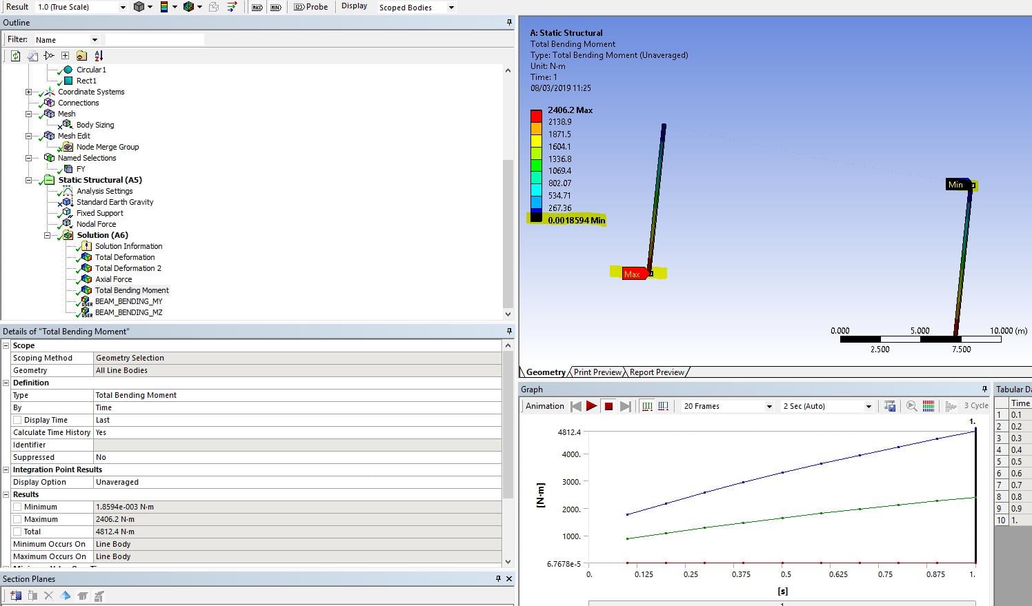
      2 columns, and 2 link180 representing a cable with a point load at the centre of the cable. As you can see it does not apply any moment on the top of the columns, and rotates like a hinge at their connections. Strand7 gives exactly the same results. 


      So there is no need to end release anything, they form a natural hinge.


    • JackieX
      Subscriber

      Thank you for the explanation. I use Design Modeler to form the lines to one part. I thought it is fix-fix connection so I use the end release on the link and beam connection. Now I get it. 

Viewing 2 reply threads
  • The topic ‘Link 180 and beam 188 connection’ is closed to new replies.
[bingo_chatbox]