-
-
January 17, 2025 at 5:43 pm
taha.muzaffar94
SubscriberI conducted a lifting analysis, one considering remote points and the other treating the sling as a rigid material. I was expecting similar results and deformations, but they turned out to be different. The deformation I am getting in a simulation with slings seem to me more realistic. I would appreciate any guidance on whether I might be doing something wrong.

-
January 17, 2025 at 10:06 pm
peteroznewman
SubscriberI suggest you create a coordinate system at the lift point then use 4 stiff springs. Each spring is to ground at the (0,0,0) coordinates of the coordinate system you created and the other end is scoped to the face on the hole that you show. The frame hanging from the 4 stiff springs is free to swing and spin so you may want to turn on Weak Springs under the Analysis Settings to help the solver.
-
January 18, 2025 at 3:20 am
taha.muzaffar94
SubscriberWhat's wrong with using slings as rigid elements and setting the junction of the slings with remote displacement (by fixing all 6 degrees of freedom)? Do the results obtained from such an approach lack realism? the sling material is polyamide and such slings can lift up to 10 tons. My aim is to calculate the angle of attack as unfavorably as possible, If the slings elongate, it will be positive for the cross struts, so I assumed slings to be very stiff, which is unfavorable for the cross struts.
Secondly, I initially attempted the simulation using stiff springs, but I encountered unrealistic results. The boundary conditions were standard Earth gravity, and I also aligned the lifting point with the center of mass of the assembly. I set the stiffnes to 1000N/mm for test purpose as it is not known to me and set the springs preload to 3500N as total weight lifting load is 12000N (1200kg).

Â
-
January 18, 2025 at 1:18 pm
peteroznewman
SubscriberRigid elements add stiffness to the structure that is not present in slings. Springs only provide axial stiffness, which correctly represents the physics. You added a preload to each spring of 3500 N, but due to the unequal angles of the springs, the tension in the springs will not be equal in the solution. You can probe the spring tension in the results and adjust the preload to match the tension and solve again. Using this approach, the spring will not elongate during the solution. I would not add spring preload but use a higher spring rate if there is excessive elongation, however stretch in the slings is part of the physics.
Taking a second look at the images in your original post, see a line body for the sling and the text mentions a rigid material. Are you saying that the line body is assigned to be rigid? Were the four line bodies meshed with beam elements? By default, four beam elements that meet at a single node will act as if they are welded together. This would cause them to act more like a structure the frame hangs from and that would behave differently to a sling. It is possible to do an end release on a beam element to allow it to pivot at the vertex node. A better method is to mesh the line bodies with a LINK180 element, which comes with a pivot at each end. However, you must make sure to use a mesh control to only allow one element per body or you will have problems solving. Using a LINK180 on each line body is like using 4 springs.
-
January 18, 2025 at 1:59 pm
taha.muzaffar94
SubscriberThanks for your detailed explanation. Actually when simulating with spring my scope was body-body which creating false result now I have change my scoping method to body-ground, this time I did'nt add the preload instead gave higher stiffness. Now is it replicating the real scenario? are stresses and deformations fine and realistic?Â


-
January 18, 2025 at 7:45 pm
peteroznewman
SubscriberOne item to change in the model then solve is under Analysis Settings. Turn on Large Deflection. This will help to give you a more realistic deformation.
The deformation plot shows the structure has swung over a little and tilted. This is because the lift point is not directly above the Center of Mass of the structure. You can find the global coordinates of the CoM in the Solution Output under the Solution Information folder. Click in the text then type Ctrl-F to find the word CENTER and there you will see the exact coordinates. Edit the coordinates of the origin of the Coordinate System you created to match the X and Y coordinates of the CoM found in the Solution Output, leaving the Z coordinate where it is.
-
January 18, 2025 at 10:17 pm
taha.muzaffar94
Subscriber -
January 18, 2025 at 10:35 pm
peteroznewman
SubscriberYou have a Remote Mass. Is that is scoped to the four feet at the bottom of the structure? I expect the Behavior of the Remote Mass is set to Deformable because I can see the feet splaying outward.
I imagine the missing structure that is represented by a point mass has some stiffness. If the missing structure had a large flat plate that the four feet bolted onto, that would add a very large stiffness that would prevent the feet from splaying out. If that is the case, you can change the Behavoir of the Remote Mass and set it to Rigid. This will be a more accurate representation of the missing structure if there is a large flat plate bolted to the feet.
I can also imagine the missing structure is a 5 sided box that is open at the top. That is a lower stiffness than a flat plate and a Rigid setting on the Remote Mass will not be so accurate.
The most accurate evaluation of the frame is to model the missing structure.
-
January 18, 2025 at 11:05 pm
taha.muzaffar94
SubscriberYes the remote mass which is actually a table is complex to model, that frame will lift the table weighing 1200kg scoped to the four feet at the bottom of the structure and it will be bolted. I have now changed point mass to rigid as it was set deformable earlier. Could you check now the deformation is fine? stresses are same they haven't changed.
-
January 19, 2025 at 7:44 pm
peteroznewman
SubscriberThe deformation looks fine. When looking at results, it is good to switch the results display scale to 1.0 True Scale to see that the deflection is only a small fraction of the thickness of the beam.
-
January 19, 2025 at 8:14 pm
-
January 21, 2025 at 7:37 pm
taha.muzaffar94
SubscriberHi Peter,
The assembly is connected using M10 bolts with nuts. Previously, I defined the bolted joint connection as a beam element without a pinball. However, I have now defined a pinball radius of 8 mm, the same as the bolt head diameter. As a result, the stresses and deformations have increased. Is it necessary to define the pinball for accurate analysis? I have attached the connection and results snaps -
January 21, 2025 at 8:13 pm
peteroznewman
SubscriberCheck the connections folder to see if any Contact were automatically created. If you are using a Beam Connection to represent an M10 nut and bolt, all the load should go through the beam and no load should go through a contact. This is a quick way to build a medium fidelity model.
Looking at the last image, a significant surface area of the tips of the legs below the spring connection has and Equivalent Stress above the red contour threshold of 235 MPa. Is that the yield strength of the material? Do you need to maintain a Factor of Safety on the yield strength? A common value for lifting structures is a Factor of Safety of 3.0. In that case, you can divide the 235 value by 3 and type in 78 MPa. It looks like some redesign is needed.
Some reduction in the stress can be obtained by spending more time building a high fidelity model. That means adding solid bodies for each nut and bolt. The nuts and bolts have frictional contact to the faces they are clamping together and frictional contact is also needed between the plates being clamped together. When all that is done, the bending of the current design will be about the bend line in the plate, which is a bit closer to the spring connection than the beam connection. I don’t think that will lower the stress enough and a redesign is needed.
A simple change is to make the plates out of thicker material. A somewhat better design is to align the plate to be in the plane of the lift spring. That way you can have the same thickness plate, but the lift spring is pulling in the plane of the plate and not trying to bend the plate. That complicates the connection to the cross-members. An even better design is to have no cross members, make four short legs bent at an angle that aligns with the angle of the springs. That way, there is just four pieces that bolt to the table with a hole at the other end for the lift slings to thread through.
-
January 21, 2025 at 9:05 pm
taha.muzaffar94
SubscriberNo I have just cross checked only beam and frictional contacts are defined, automatic connection option is turned off. Yes 235MPa is the yeild strength of material. In general practice what I do is to make sure globaly stresses should remain below yield strength. If stresses are high locally mean the areas which are loaded beyond the yield point then I use so-called ‘Neuber Hypberbel’ via ‘User Defined Result’.I check the plastic strain by using expression seqv^2/(200000*235) in user defined results, if it is <1% then strength of the structure is fine and will not plastically deform. In my case max plastic strain is 0.8%
Â
-
January 21, 2025 at 10:49 pm
peteroznewman
SubscriberAnother approach for evaluating the safety of lifiting structures is to use a non-linear Elastic-Perfectly Plastic (EPP) material model. Another common requirement is the mass of the object being lifted is doubled to provide a margin of safety. Then with the doubled mass and the EPP material model, the output from Ansys is Total Strain which is the sum of Elastic and Plastic Strain. This is compared with the Elongation at Break for the material to compute the Factor of Safety.
When using an EPP material model, if the full section of the material doing the lifting exceeds the yield strength, the EPP material will just stretch forever until the solver fails. This indicates that the design cannot pass the test. Â
When looking at a model that has a linear elasticity model, if I see red through the full section, that is a sign that an excessive amout of plastic strain will be found when the EPP material model is used.Â
If you are curious to try this let me know and I can provide more details.
-
January 21, 2025 at 10:57 pm
taha.muzaffar94
SubscriberYes please share detail/steps I can check with such approach
-
January 22, 2025 at 1:24 am
peteroznewman
Subscriber
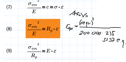
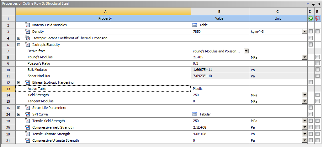
Open Engineering Data and in the Plasticity section of the Toolbox, drag a Bilinear Isotropic Hardening material model and drop it on your frame material. There are only two entries: Yield Strength and Tangent Modulus. Make sure the Units are set properly when you type in the Yield Strength value. The Tangent Modulus = 0. This is a conservative value because it says that once the stress reaches Yield, that element cannot carry any more load. As the load increases, that material just stretches and adjacent elastic material picks up the load increase until it turn plastic.
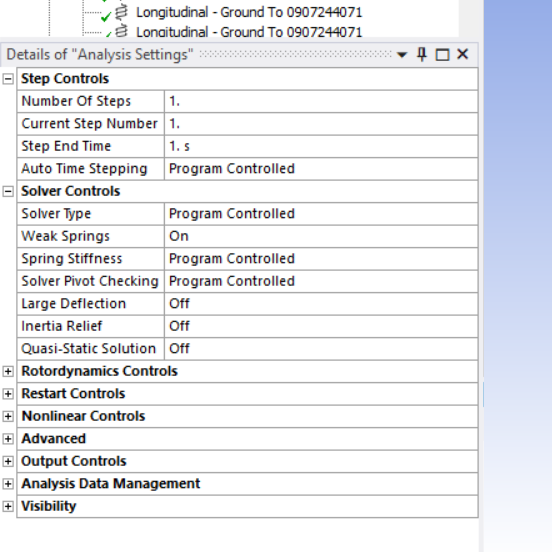
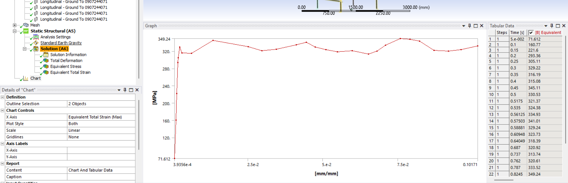
This is now a non-linear model so in Mechanical, under Analysis Settings, turn on Auto Time Stepping and set the Initial and Minimum Substeps to 20 and the Maximum to 200. Turn on Large Deflection. The solution will take longer than before.
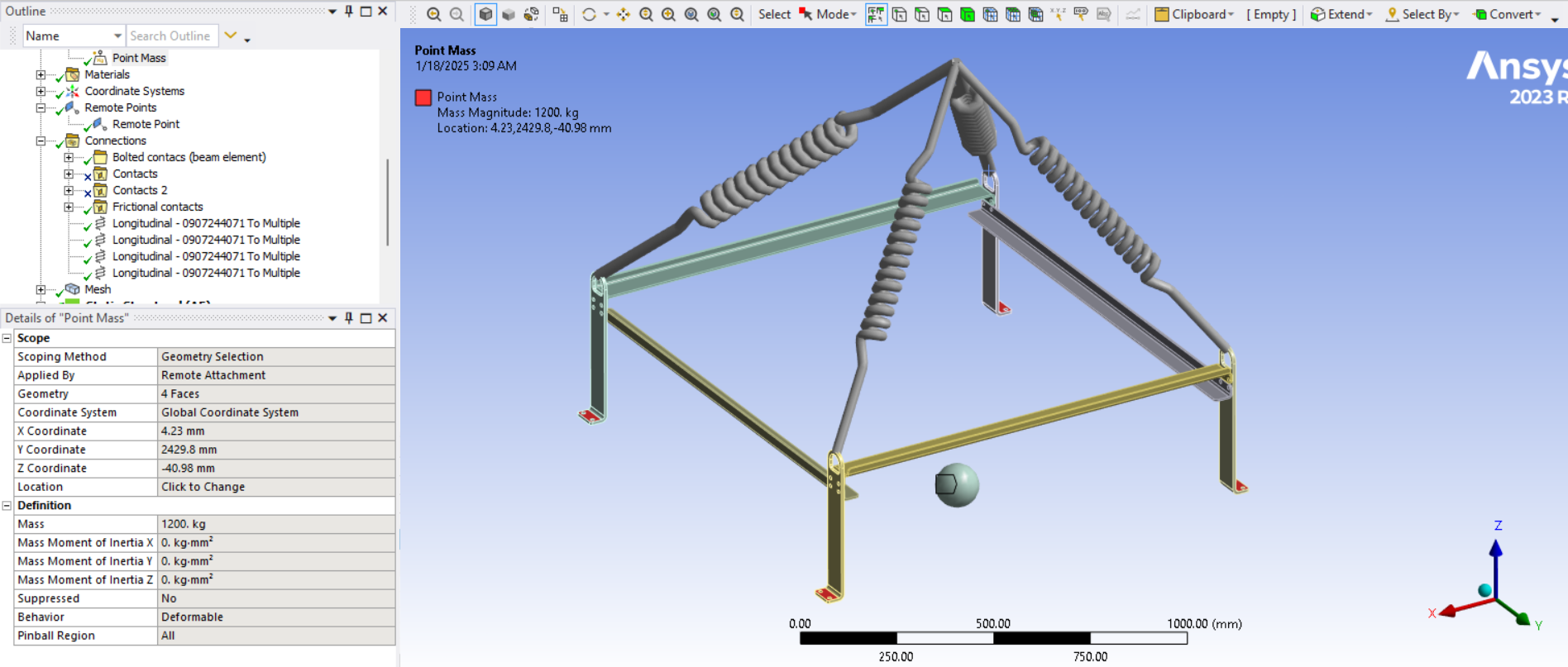
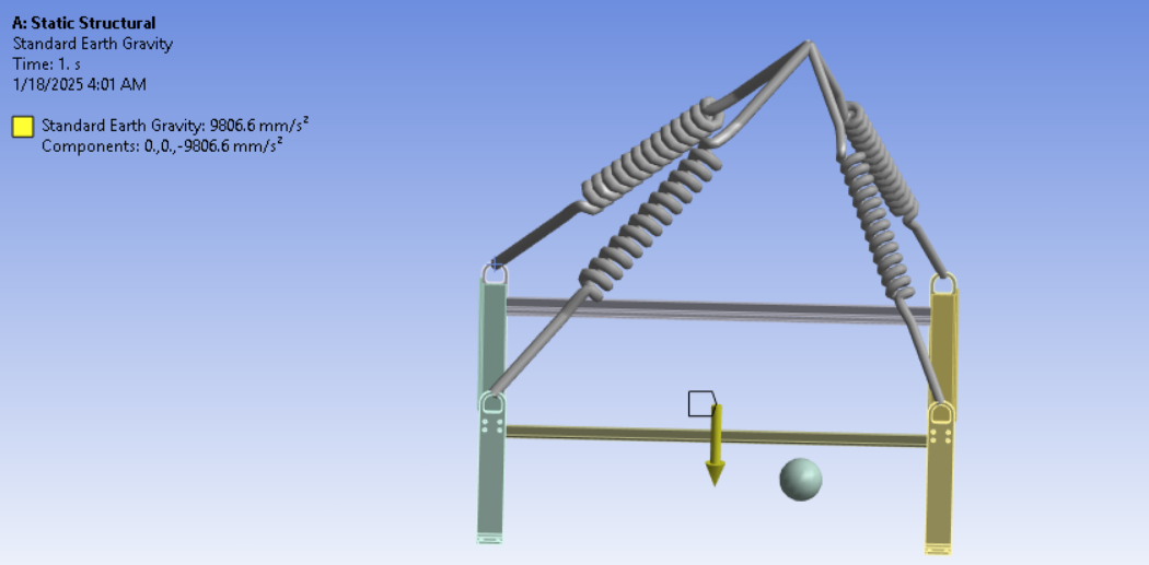
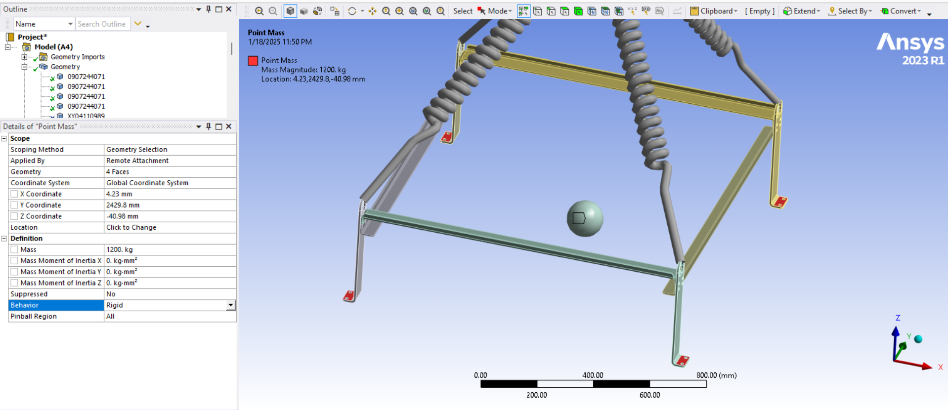
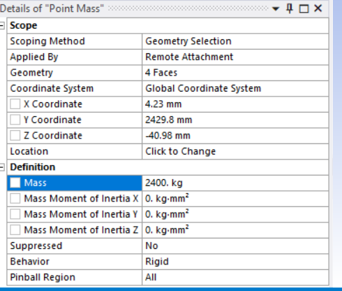
Edit the Point Mass and double the value for a load factor of safety of 2.
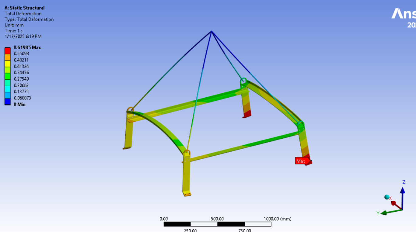
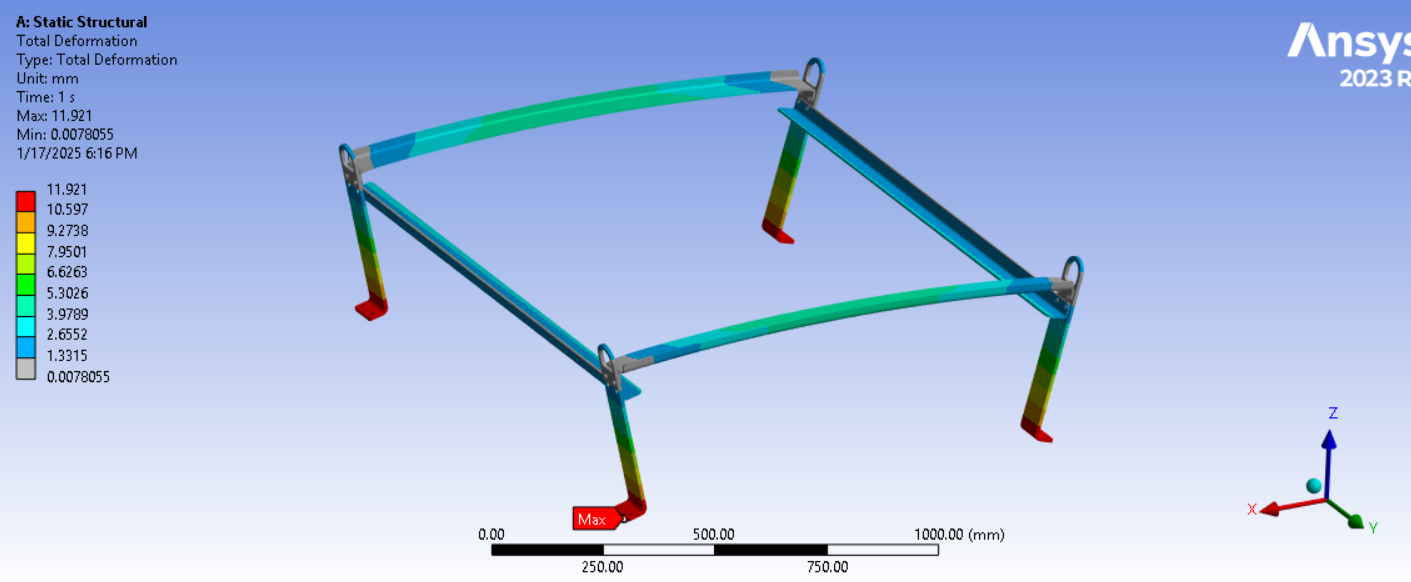
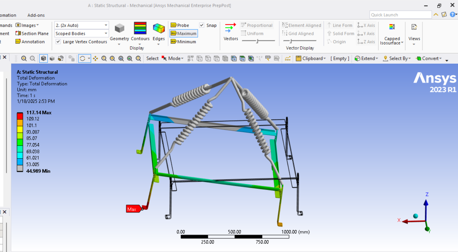
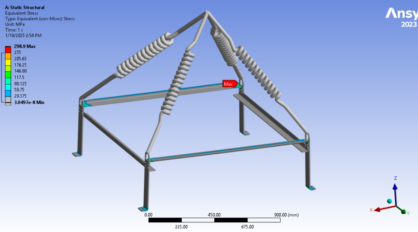
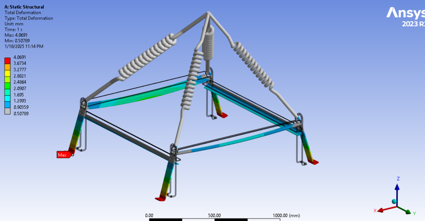
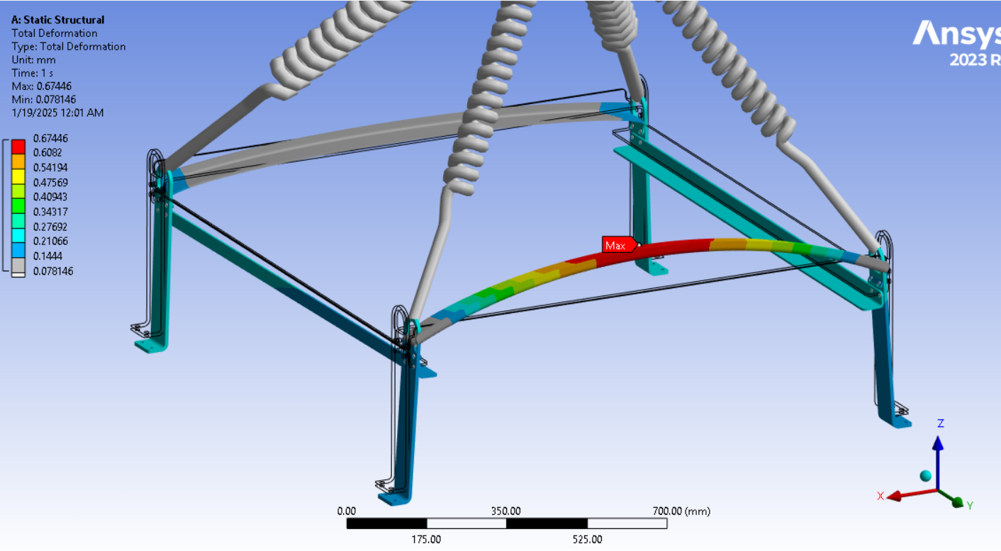
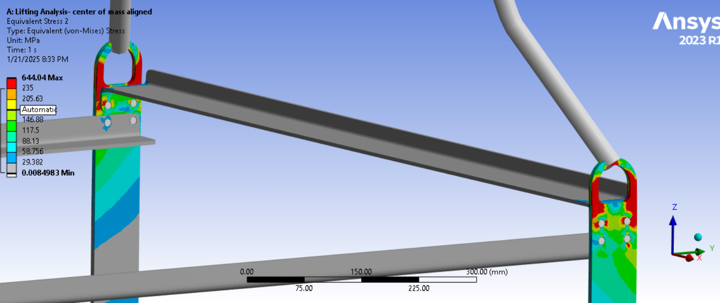
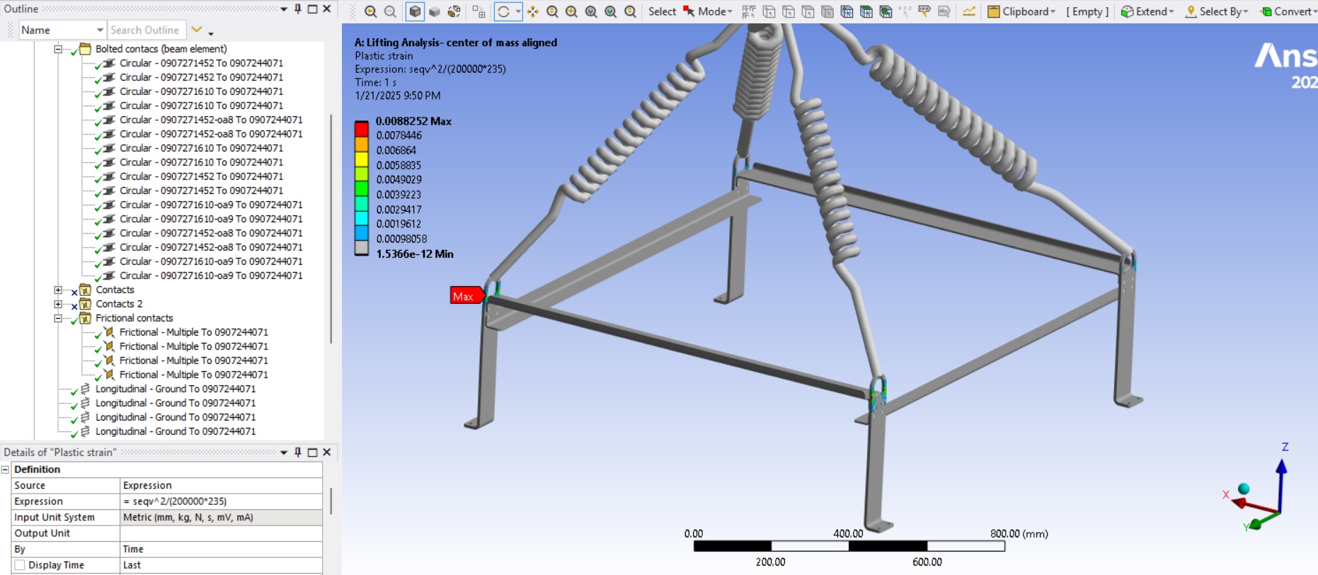
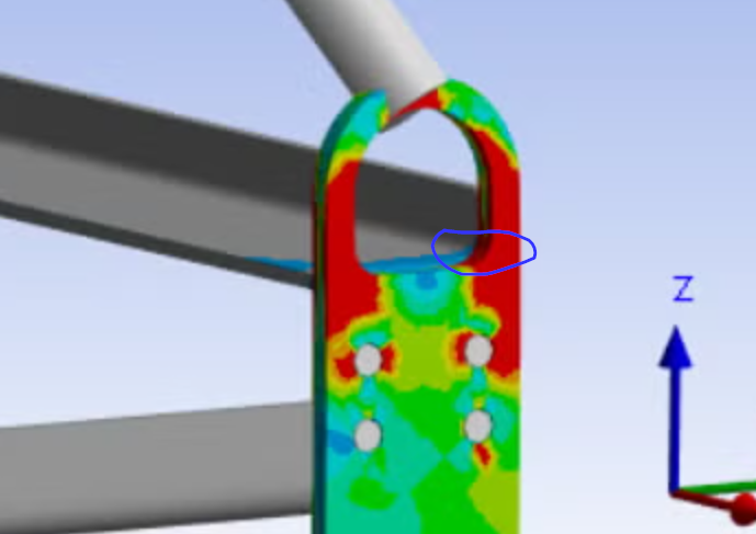
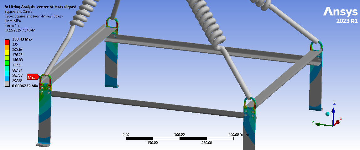
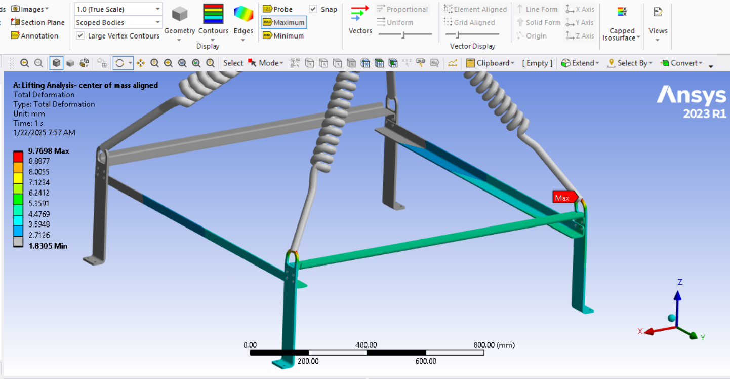
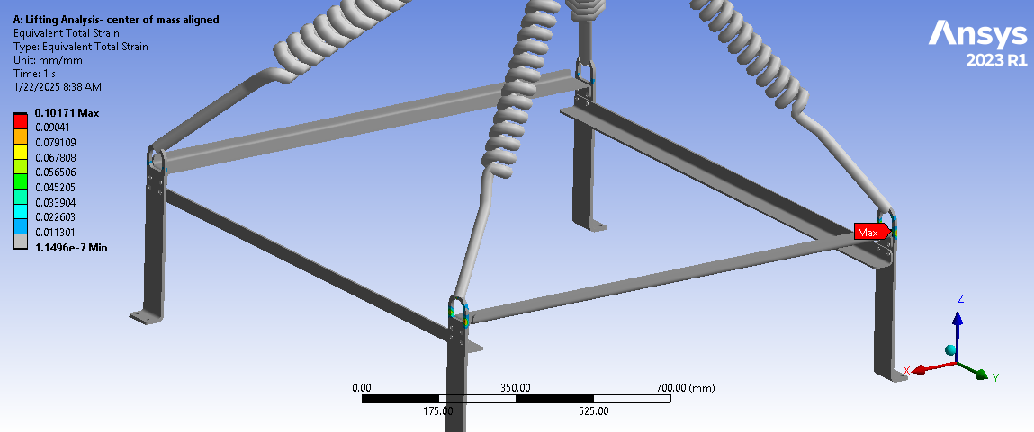
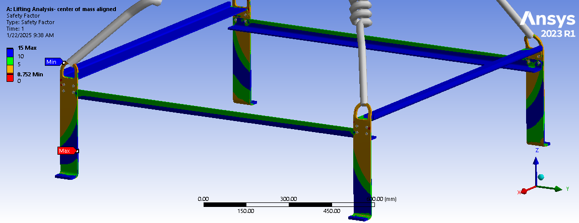
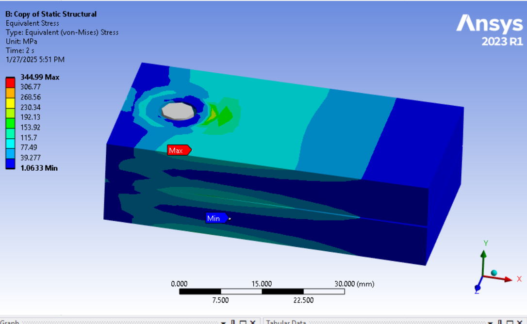
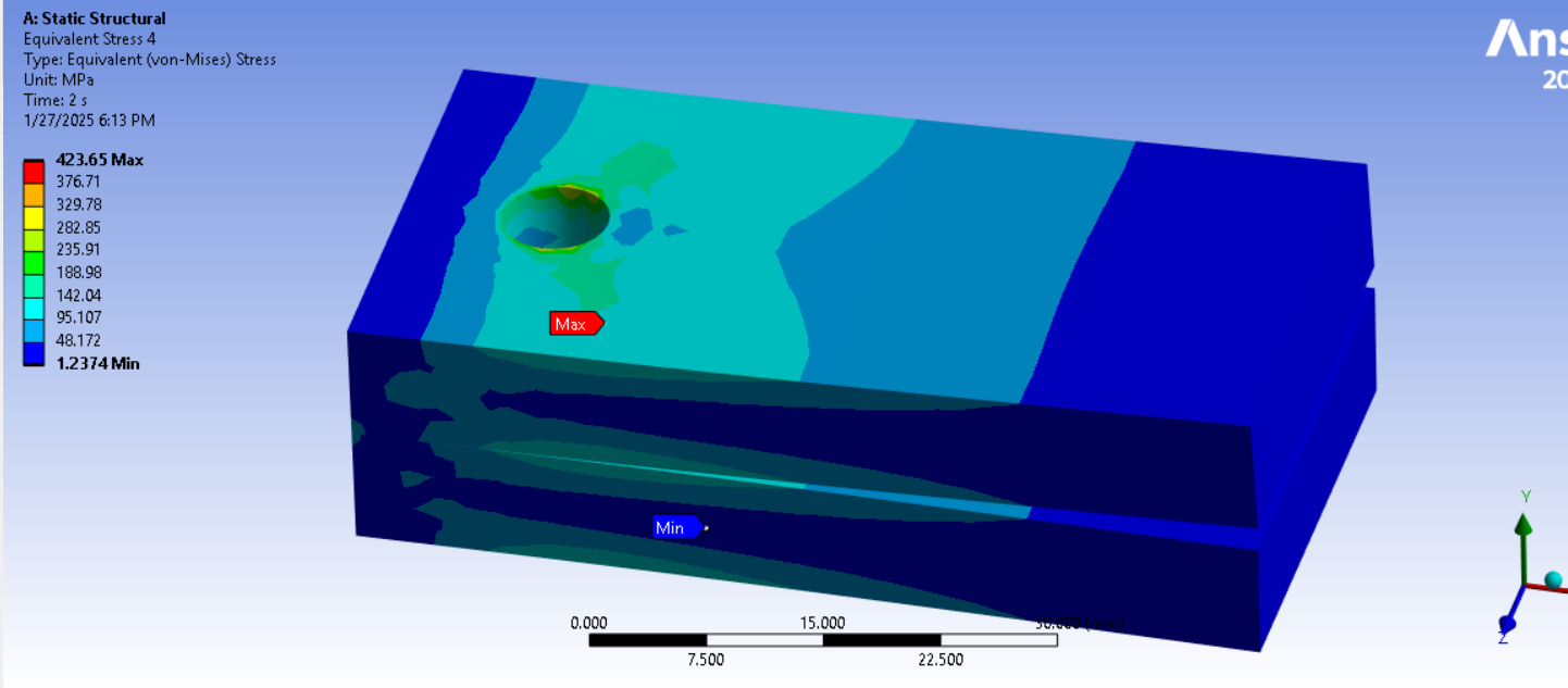
If the model converges, plot the Total Strain. Calculate the material factor of safety = Elongation / Total Strain. If the material factor of safety > 2.0 then the design has an overall factor of safety > 4.0 since the load is at a factor of 2. This is how you can check that the design is a long way from a potential failure.
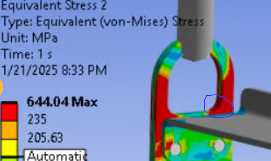
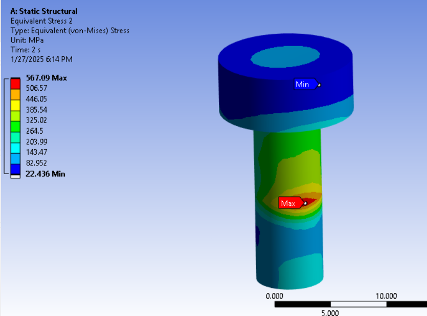
If the model doesn’t converge, that is likely to be because the cross-section is approaching a fully yielded state. You can check the last converged substep and check the Total Strain with only a fraction of the gravity load ramped on.
-
January 22, 2025 at 8:34 am
-
January 22, 2025 at 8:43 am
-
January 22, 2025 at 1:13 pm
peteroznewman
SubscriberWith linear elastic materials, you compare Yield Strength with Equivalent Stress. Once you introduce an Elastic-Perfectly Plastic (EPP) material, you stop looking at stress and you start looking at Total Strain. The reason is the stress doesn't increase much above the Yield Stress due to the EPP material stress-strain curve.
Elongation at Break or simply Elongation is a material propery just like Tensile Yield Strength. You need to look up that value for the specific material you chose to make the structure from. Ductile materials have a large Elongation such as 30% or more. Brittle materials have a small Elongation such as 1% or less.
Your Total Strain is 10% so choose a material with an Elongation at 20% and this design could work. If you choose a material with an Elongation of 5% then you should redesign.
I mentioned some design alternatives that will have much lower stress and total strain that you can analyze.
-
January 22, 2025 at 4:18 pm
taha.muzaffar94
SubscriberThanks alot.
-
January 25, 2025 at 4:58 pm
taha.muzaffar94
SubscriberHi Peter,
When defining a bolted joint using a beam element in the detail window, we need to select a behavior type: rigid, deformable, or beam. I am confused about which option is the most appropriate in this case. The results were based on deformable behavior. How do we determine the correct option to select?
-
January 25, 2025 at 7:06 pm
peteroznewman
SubscriberAt each end of the beam element is a node at the center of a hole. That node is scoped to some geometry such as a face or an edge of a hole in one of the parts being connected. Suppose there are 24 nodes on that face or edge. A spider of elements is created from the node at the center of the hole to each of the 24 nodes around the hole.
The behavior sets what kind of stiffness exists in that spider. The choices are rigid, deformable and beam. Rigid means the 24 nodes are rigidly connected to the center node and so the spider adds local stiffness around that hole. This is a good option. Deformable means that the center node moves with the average motion of the 24 nodes so this spider does not add any stiffness to the hole.Â
The bolt head or nut does add some stiffness to the hole so deformable is not as good. Finally, each leg of the spider can itself be assigned a beam cross-section and material, which is the beam option. That allows a compromise between rigid and deformable but I don’t usually go with that and prefer to add a solid body nut and bolt to the model if I want higher fidelity to the real conditions.
A more significant upgrade to a higher fidelity model is to add bolt pretension. Here are two videos reviewing beam connection vs solid body threaded nut, both videos using bolt pretension.
-
January 27, 2025 at 10:01 am
taha.muzaffar94
SubscriberThank you for your detailed answer. Based on the videos you provided, I also reviewed this and found that the stress pattern and values near the hole in the beam connection when set to rigid are lower compare to bolt as solid body. (deformation is not set to true scale in screen shots!!)
When I set the beam connection to deformable in detail window in both (reference and mobile ), the stress distribution is quite similar near bolt hole unlike when set to rigid.Â
-
January 27, 2025 at 12:36 pm
peteroznewman
SubscriberGood to see you learned how to do a solid nut and bolt with pretension. This is the best option but is more work. To do less work, say because there are a lot of nuts and bolts, you found deformable connection to each end of the beam delivered stress closer to the solid nut and bolt.
Was the beam connection scoped to the cylindrical face of the hole? That doesn’t simulate the solid nut and bolt as closely because the face of the bolt head and the face of the nut touch the top and bottom faces of the plates they are clamping. A more realistic way to use beams is to imprint a circle on each face that is equal to the diameter of the washer if used or the nut or bolt head and scope the ends of the beam to the new faces of the plates.
-
January 27, 2025 at 2:31 pm
-
January 27, 2025 at 2:43 pm
peteroznewman
SubscriberPinball radius is a great time saver over imprinting circles on faces. Just need to make sure that the element size around the edge of the hole is well controlled to spread the load the way you want. You can visualize the connection elements after solution by clicking on the Solution Information folder and then click the tab at the bottom of the main window to Geometry.
-
January 27, 2025 at 3:08 pm
-
January 27, 2025 at 3:33 pm
peteroznewman
SubscriberOne refinement to the beam connection is to edit the coordinates of the threaded end of the beam to the top of the threaded hole. This will shorten the length of the beam that will slighly increase the stiffness of the beam. The reason is most of the load from a threaded shaft to a threaded hole is transfered in the first few threads. The default location for the beam end is the center of the cylindrical hole that it is scoped to which creates a longer beam. It is one extra step to change the location to the center of the edge, while leaving the scope on the cylindrical face.
The best option is going to be deformable. Note that you don’t pay close attention to the stresses around the threaded hole when using a beam connection. Evaluation of the safety margin of threaded holes is done using a hand calculation outside of Ansys. The important information that Ansys can provide are the forces and moments going through the beam connection, specifically the axial force and the shear forces and moments. These forces can be compared to the strength of the threaded portion of the bolt. As the bolt preload increases, the moments should be reduced as the material around the hole should be fully clamped and not gapping, causing moments to arise in the bolt that can lead to fatigue failure.
-
January 27, 2025 at 5:20 pm
taha.muzaffar94
SubscriberDoes the best option (deformable) applicable for only threaded bolts? or for clamped with nut too?Â
Below are the results based on scoping on the the beam to the top of the threaded hole while leaving the scope on the cylindrical face. (Shortened beam length)
Behaviour: Deformable --->
Behaviour: Rigid --->
Solid Bolt -->
Â
-
January 27, 2025 at 7:12 pm
peteroznewman
SubscriberIn the 2-step analysis with step 1 being bolt pretension and step 2 being a cantilever load to pry apart the plates, I see evidence that a gap is opening on one side of the bolt hole and causing bending in the bolt which can be seen in the solid bolt shaft. This shows that the bolt preload is inadequate to support the cantilever load. If a gap is allowed to occur in the clamped interface, bending moments will arise in the bolt which should only carry axial tension.Bending moments can lead to fatigue failure of the bolt if the cantilever load cycles on and off. Use the Contact tool in the Solution branch to plot the pressure result on the contact surface between the clamped plates to see if the pressure drops to zero on one side.
 As bolt preload increases, material around the hole should become fully clamped, not allowing any gap to form on one side and maintaining a positive contact pressure around the hole as the cantilever load is applied in step 2. It would be best to apply more preload before you evaluate the stress in the parts.
For a solid bolt with a threaded end, there is one more refinement to even more realisticially distribute load through the threads, and that is to use the Contact Geometry Treatment on a Frictional interface as described here: https://innovationspace.ansys.com/forum/forums/topic/simple-method-for-simulating-local-deformation-near-fastener-threads/ Â Change the Bonded Contact to Frictional contact to proceed with this, but pay attention to the meshing requirement of 4 elements per thread pitch.
The solid bolt approach is the most realistic representation. If you want to save time, use a Beam Connection with Preload. Once the preload is sufficiently high, the difference between Deformable and Rigid spiders at each end of the beam connection may begin to matter less, but if you want to show the difference, please show just the part with the highest stress and rotate the view to see it. Also, use identical color legend scales so it is easier to compare between the two types as the legend will be the same.
-
- You must be logged in to reply to this topic.
-
5884
-
1906
-
1420
-
1306
-
1021
© 2026 Copyright ANSYS, Inc. All rights reserved.


