-
-
November 20, 2024 at 6:06 am
z5456415
SubscriberHi all,
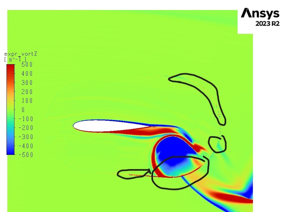
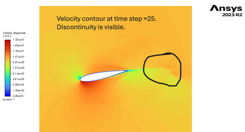
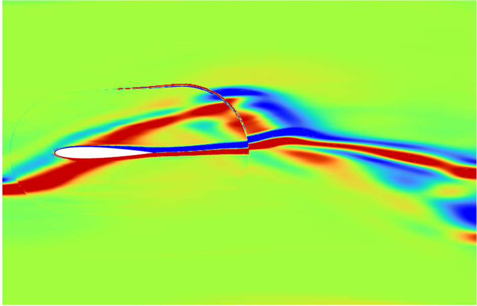
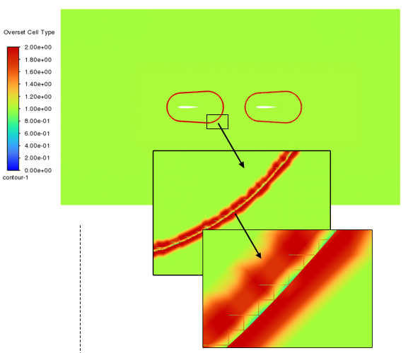
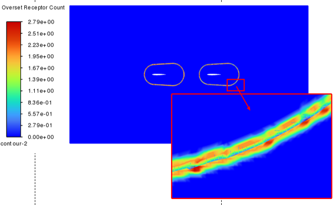
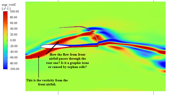
I am encountering an issue with contour plots for a pitching airfoil simulation (using a dynamic rotating mesh). The contour shows a discontinuity between the dynamic mesh zone and the background mesh. Please refer to the attached image for clarity.
Additionally, the contour plot displays the edge of the dynamic mesh zone, even though I did not select it when defining the contours.
Can anyone please assist me in resolving this problem? I am saving the contours at each time step by defining an animation under Solution Animations (in Calculation Activities) and exporting them as JPEG or PNG files. Would using ANSYS Ensight for postprocessing help address this issue after saving the files as HSF?
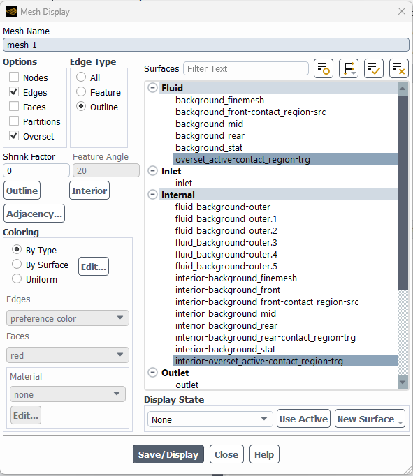
I also tried selecting only the background mesh and airfoil boundaries (excluding the dynamic mesh zone), but this created a gap (an empty region) between the airfoil boundary and the background mesh in the plot.
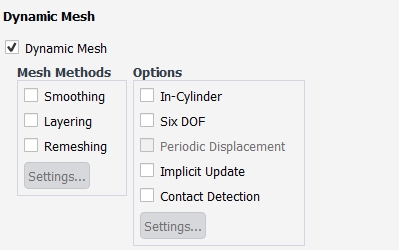
I need to use the dynamic mesh option for this simulation because I plan to simulate passive airfoil motion later (the current simulation shows active motion).
Any suggestions would be greatly appreciated!
Regards,
Muhammed Sadique
-
November 20, 2024 at 10:08 am
Rob
Forum ModeratorPlease can you post an image of the mesh and also velocity contour.
-
November 21, 2024 at 12:43 am
-
November 21, 2024 at 12:05 pm
Rob
Forum ModeratorOverset? How does the contact look, ie how many orphan cells are there?
-
November 25, 2024 at 11:27 pm
z5456415
SubscriberYes, Overset mesh, where the dynamic motion is defined using the Dynamic mesh option (not using cell zone conditions). I did this because later I will need to prescribe/define motion passively using an equation.
I do not know how to check for orphan cells. Could you please advise me on this? when I am using "/define/overset-interfaces/check" the console shows as below
And when I checked Mesh under graphics it displayed the overset mesh as below.
It would be so helpful if you could help me on this.
-
November 26, 2024 at 2:12 pm
Rob
Forum ModeratorYou'll get a warning about orphan cells in the console if there are any.
You should be able to see the overset cell types in a Contour plot, possible under Cell Info. Posting an image of the mesh may not be overly useful here as I can only see green. The first mesh image looks to have a fairly big cell size mismatch hence my question regarding orphan cells.
-
February 6, 2025 at 7:18 am
z5456415
SubscriberI did the following to reduce the discontinuity in contour.
define/overset-interfaces/options/donor-priority method [1]: boundary distance based
define/overset-interfaces/options/expert yes
define/overset-interfaces/intersect-all yes
However, it is not resolved. I am using the mesh where the mesh size of the overset region matches the background region. see the image below.
I checked the orphan cells using TUI and which gives the result as follows,
-
February 6, 2025 at 11:05 am
Rob
Forum ModeratorIf you plot the cell type (donor, acceptor, orphan etc) does anything explain the flow contour?
-
February 18, 2025 at 1:50 am
z5456415
SubscriberHi,
This is the contour I get when I plot overset cell type.
This is the contour of cell element type.
Overset donor count,
overset receptor count
Apart from discontinuity, there is another issue with the flow field. the flow does not seem to interact with the airfoil.
Should I use any additional TUI commands (apart from the commands I mentioned in my previous reply) to solve the issue with orphan cells and sort this out?
-
February 18, 2025 at 11:37 am
Rob
Forum ModeratorThere's something else going on in that case. Does the model work with only one airfoil?
-
February 18, 2025 at 10:57 pm
z5456415
SubscriberHi, thank you for your reply. I did not check the flow field with a single airfoil. However, for validation purposes, I simulated a single airfoil and compared it with experimental results (Cl &Cd). Those results are reliable and reproducible.
Also, please note that in the dynamic mesh motion, I did not check any options (smoothing, layering, or remeshing). When I check any of these options, it causes a negative cell volume error.
-
February 19, 2025 at 12:00 pm
Rob
Forum ModeratorYou're not remeshing as it's overset: those other options are for when the cell shapes change.
If a single overset airfoil works, what is different in the current model?
-
February 19, 2025 at 11:09 pm
z5456415
SubscriberAs I mentioned before, there is no issue with the values (Cl, Cd, Cm, velocity in x and y direction) obtained from the model. I confirmed this by using the model with a single airfoil oscillating sinusoidally and comparing the results obtained with existing literature. The issue arises while generating the contour plot. The issue is the discontinuity in the flow field while looking into the contour plot.
Please note that there is not difference in the model while using 2 airfoils. Both airfoils oscillate using an overset mesh.
Do I need to choose any options from the dynamic mesh (even though I am using an overset mesh for the simulation), or do I need to use any TUI commands to suppress the discontinuity?
-
February 20, 2025 at 11:40 am
Rob
Forum ModeratorOK, are the airfoils overlapping at all? If a model works with one foil it should be fine with two. To check, the boundary conditions etc are all unique to each overset block?
-
February 20, 2025 at 11:47 am
z5456415
SubscriberAirfoils do not overlap each other. The boundary conditions are unique for both overset blocks, which are applied to the inlet, outlet, bottom, and top walls of the big domain. Also, no-slip conditions on airfoils
-
February 20, 2025 at 12:02 pm
Rob
Forum ModeratorCan you zoom out so show flow field for both foils? And overlay the overset boundary location.
-
- You must be logged in to reply to this topic.
-
3019
-
970
-
857
-
761
-
599
© 2025 Copyright ANSYS, Inc. All rights reserved.