-
-
September 23, 2024 at 2:19 pm
mohalinasre2001
SubscriberHello,
I am currently simulating a VAWT using ANSYS Fluent. However, I am getting wrong results compared to the experimental ones.
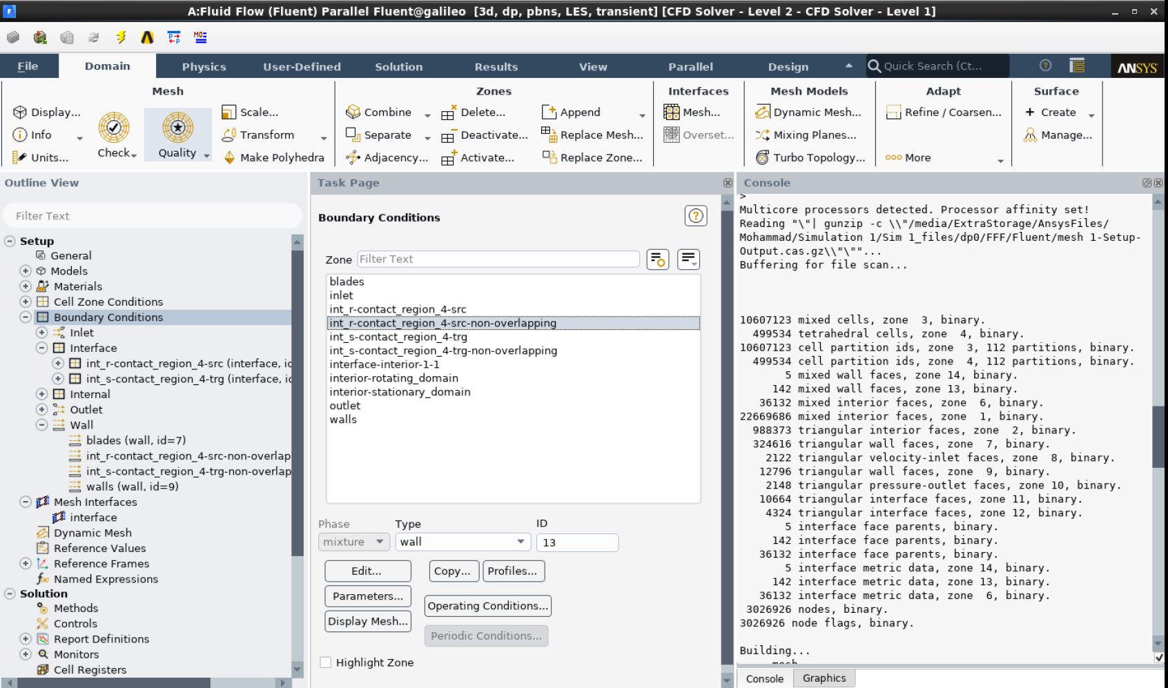
While checking the boundary conditions, I realized that when I created the interface between the "stationary" and "rotating" domains, 2 non-overlapping surfaces are created in the boundary conditions and are set as "walls". I don't know if this is what is causing the problem, does anyone have any idea?
Attached is a screenshot showing the surfaces created as walls in the boundary conditions. (I can't change them into interface).
Thank you so much for your help!
-
September 23, 2024 at 2:24 pm
Rob
Forum ModeratorA Non overlapping wall is there to cover for when the two sides of the interface pair don't line up. If you right click on the Mesh interfaces (I think, unless it's the actual pair in boundary conditions) there's a summary/report option. That should show 100% (well, over 99%) contact. If it doesn't you have a problem and need to look at the flow results rather than just numbers.
-
- You must be logged in to reply to this topic.


-
3432
-
1057
-
1051
-
897
-
896

© 2025 Copyright ANSYS, Inc. All rights reserved.


