TAGGED: #fluent-#ansys, dispersed-particles, fluent, injection, particles
-
-
August 7, 2024 at 8:16 pm
blanca.cerda
Subscriber -
August 8, 2024 at 10:05 am
Rob
Forum ModeratorYou're wondering why the particles don't follow the expanding flow? Why would they?
-
August 8, 2024 at 8:32 pm
-
-
August 9, 2024 at 9:06 am
Rob
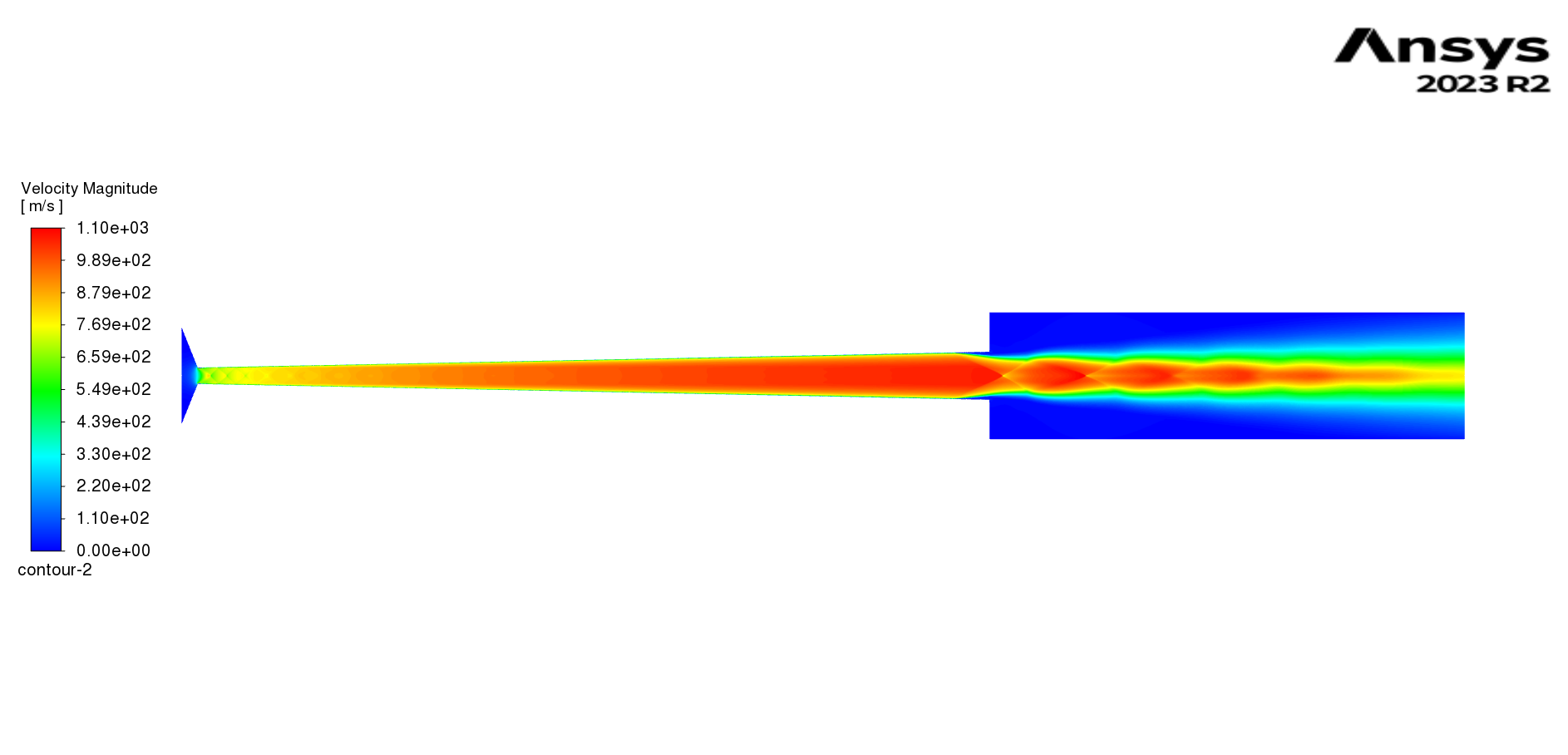
Forum ModeratorHow does the flow field look in your case? Why are the particles accelerating along the expansion nozzle and further into the plenum? Is that 2d or 2d-axi symmetric?
-
August 11, 2024 at 3:32 am
-
August 12, 2024 at 8:49 am
Rob
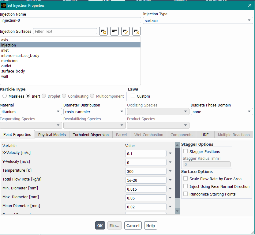
Forum ModeratorGet rid of the size distribution and try a uniform particle size, set the injection mass for that size range. Add a few sizes (you can copy most of the injection settings). Do smaller particles follow the flow better than larger ones? Have you checked the titanium density?
-
September 1, 2024 at 5:07 am
blanca.cerda
SubscriberI tried what you said, and i tried different things but happens the same.
I am working the flow with SST k-omega, but i tried standard k-epsilon and this changed, and i got what i needed.
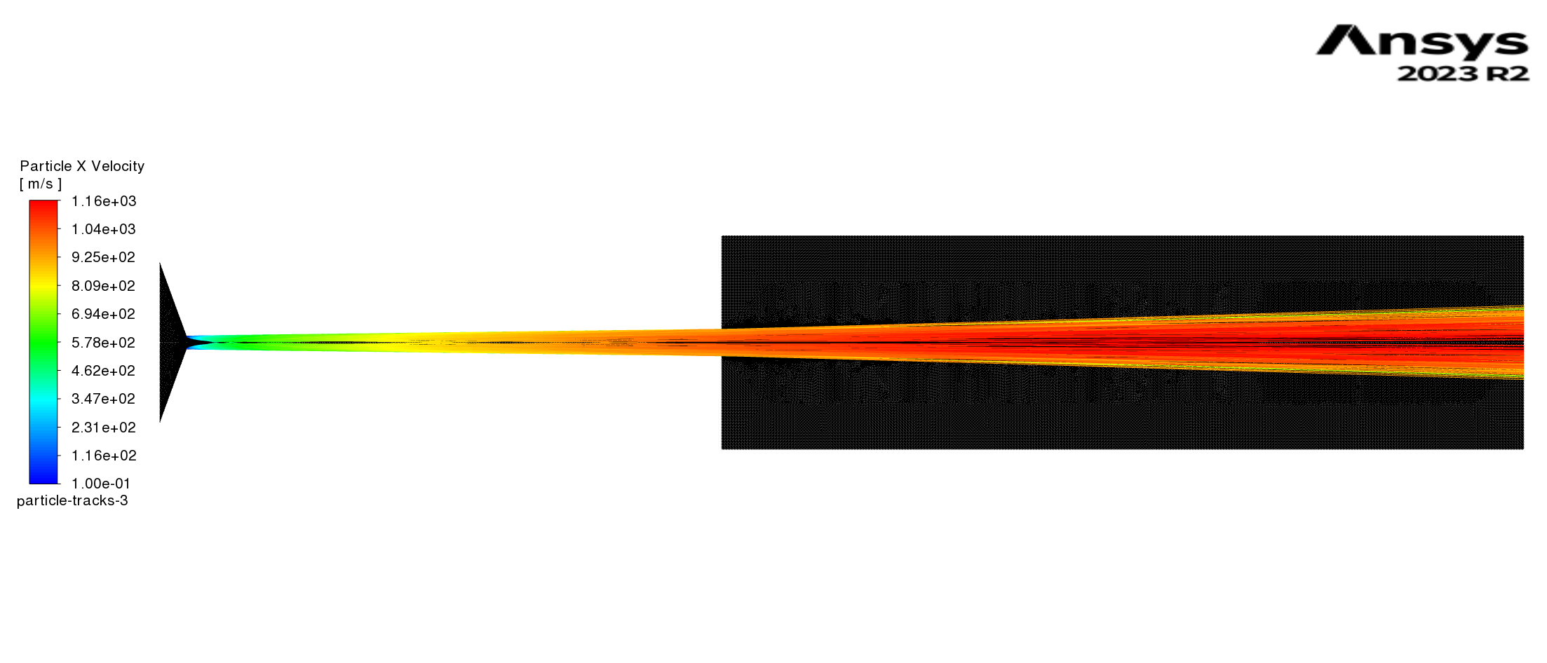
this is what happens with k-omega,
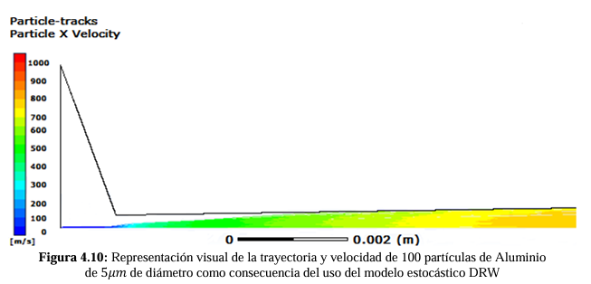
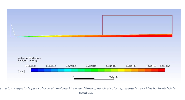
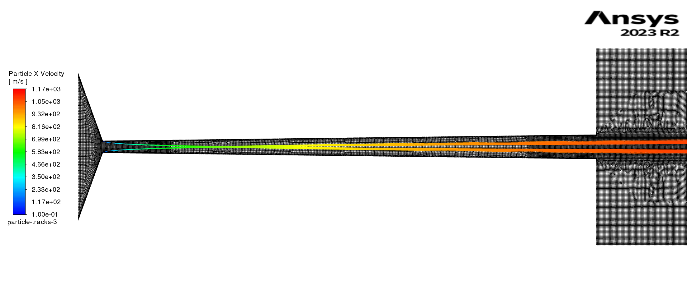 But, even I have the same results for both for the flow, this changed with the particles, do you have if this is really something that can happen or should i consider something else if i am using sst k-omega for the particles?
Thanks in advance -
September 9, 2024 at 9:19 am
Rob
Forum ModeratorWhy do the tracks appear to start at the entrance to the nozzle in the two more recent images? k-e and k-w should give much the same result away from the wall, but given this is a high velocity jet I'd also consider RSM: read up on the 2-equation models and their limitations to understand why.
-
September 10, 2024 at 5:50 pm
blanca.cerda
SubscriberIn the last two images the injection start at the throat of the nozzle, this is something of the setup, nothing actually related or that influence this behaviour, because i also tried injecting the particle from the entrance and they have the same differences. I read both equations, but simply this doesnt make any sense. for the same configuration of fluid dinamic study and the particles, with just the difference of the turbulence model.
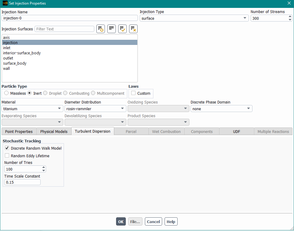
In order to obtain the result i expected, i needed a Time Scale Constant for turbulent dispertion of 10 inseat of the 0.15 but i search about this and it would be ok to use 0.15 for k-omega model, and it doesnt make sense such difference between two models, because i used 0.15 of time scale for k-epsilon. The only information i got about this, is this: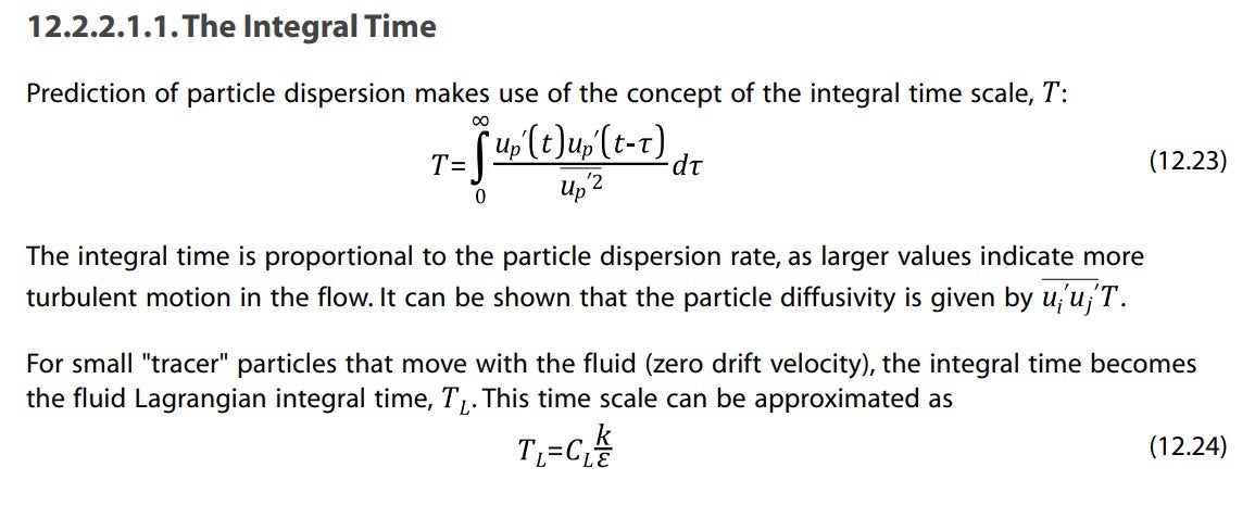
it suggest to change epsilon for 0.09k/omega, in the equation 0.024 but it doesn't explain too much about the C_L. It says its not well know bot they got an aproximation that is not explained too.
-
September 11, 2024 at 11:03 am
Rob
Forum ModeratorAt the speeds you're seeing chances are there is enough compression/expansion of the flow to divert the particles. As each turbulence model will interact differently that could cause the banding. How many stochastic tries did you use?
-
September 23, 2024 at 6:21 pm
blanca.cerda
Subscriberthis behaviour have no explanation for me as you said there's enough compression/expansion of the flow to divert the particles. In this comparison (k-epsilon and k-omega cases) I used 100 stochastic tries.
Even if i use more tries, like 1000 it looks the same, where the particles doesnt even get close to the wall for the k-omega model.100 tries, using time scale 0.3 suggested in others post for k-omega

-
September 24, 2024 at 10:14 am
Rob
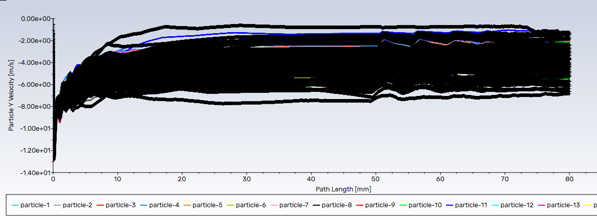
Forum ModeratorHow does the y-velocity look? How does that compare to the dimension and flight time? Ie is it just that particles don't remain in the domain long enough for the jet to expand.
-
September 24, 2024 at 4:02 pm
-
September 24, 2024 at 4:24 pm
Rob
Forum ModeratorOn the particle tracks there's a time value to report.
The two models are slightly different in the near wall region, given the flow field that may extend into the bulk of the throat. At the speed you're seeing small changes may be sufficient to cause a larger change in the trajectories.
-
September 24, 2024 at 5:54 pm
-
-
- You must be logged in to reply to this topic.


-
3467
-
1057
-
1051
-
918
-
896

© 2025 Copyright ANSYS, Inc. All rights reserved.

