TAGGED: eigenvalue-buckling, implicit, ls-dyna, theory
-
-
August 19, 2024 at 3:08 pm
fabian.duckhorn
SubscriberComparing the results of my (implicit) nonlinear transient buckling analyses of a sandwich panel using the Arc Length Method with a simple Linear Eigenvalue buckling analysis (also implicit), I observe a difference of only 2 percent in the calculated maximum buckling load. According to the literature, there should be a much larger difference due to the linearity, and the calculated buckling loads of the Linear Eigenvalue buckling analysis should be significantly higher. Therefore, I am now investigating why the results are so "lucky," but I don’t fully understand the simplifications made in this method and the influence of the base simulation, which is nonlinear in my case. From what I understand, the base step is used to set up the stiffness matrix that corresponds to the stresses from the reference load. Is it possible that by using initial stresses from the preforming step, the calculated stiffness matrix describes a stiffer behavior because the initial stresses add to the total stresses caused by the external force? Since initial stresses are not considered in the linear eigenvalue buckling analysis, the stiffness matrix is seen as a reaction only to the reference load, and therefore the buckling load is calculated to be smaller. Is this assumption correct ? This would also explain why using a smaller reference load is causing the calculated buckling load to be even smaller than the exact buckling load, because the proportion of the initial and force related stresses is bigger.
-
August 28, 2024 at 2:05 pm
dlooman
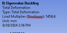
Ansys EmployeeWith a purely linear buckling analysis the load used in the prestress analysis should have no effect. The legend in the buckling analysis indicates whether the analysis was considered to be linear or nonlinear. (In a nonlinear eigenvalue buckling analysis the buckling load is the sum of the prestress load and the eigenvalue load.) I agree that one would expect the eigenvalue buckling load to be much higher than a large deflection analysis if the panel is very thin and unstiffened. What are the dimensions of the panel?
-
August 28, 2024 at 4:53 pm
fabian.duckhorn
SubscriberThank you for your reply, the panel measures 195x195x26mm and is made of two thin metal sheets, modeled with a fully integrated shell element, with a thickness of 0.5mm. One of the facesheets is preformed so that some areas are dented outwards and therefore sticking out. Those dents are then connected to the second facesheet so they act as a core and hold the distance between the facesheets.
I have tryed the simulation without the initial stresses and i now got a difference of 2.3%.
Can you explain what legend you are refering to ?
I have seen that with ansys mechanical you need to add 1 to the load factore however in ls-dyna i cannot find any information for this. Is this rule also applying to ls-dyna?
Where can i find such information ?
-
August 28, 2024 at 6:40 pm
-
August 31, 2024 at 1:12 pm
fabian.duckhorn
SubscriberNow i understand what legend you are reffereing to. Unfortunately i am not using the Workbench for my analysis. After some more research i found that when using the ls-dyna solver directly the eigenvalue of the eigout file always represents the load factor and it does not matter if the base simulation is linear or nonlinear. Therefor i assume that the good results are due to the small deformations at the buckling load and the low stresses in the material that are within the elastic range. In the Guidlines for implicit analysis it says that imperfections are also neglected. Can you explain what those imperfections are ? if the imperfection would be a dent then this would be included in the stiffnessmatrix as i understand this.
-
- You must be logged in to reply to this topic.


-
4607
-
1510
-
1386
-
1209
-
1021

© 2025 Copyright ANSYS, Inc. All rights reserved.


