-
-
April 18, 2024 at 5:55 pm
be21b028
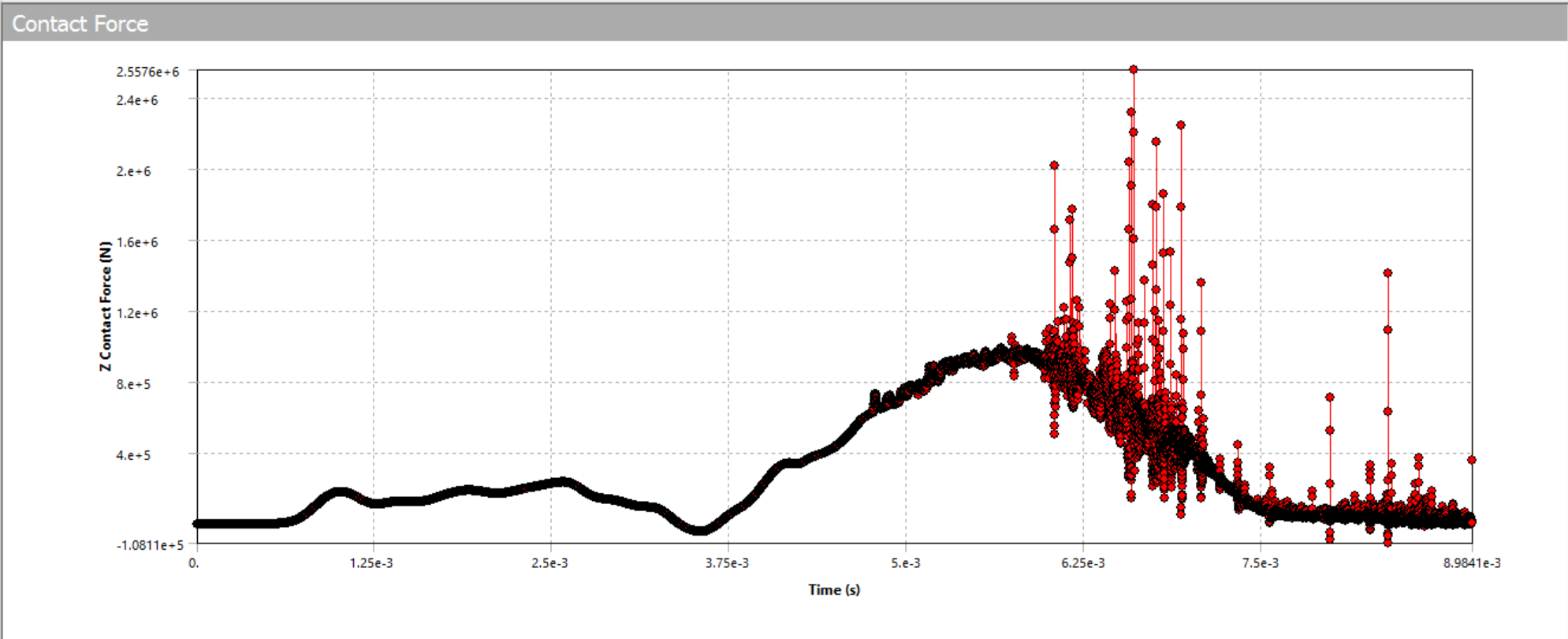
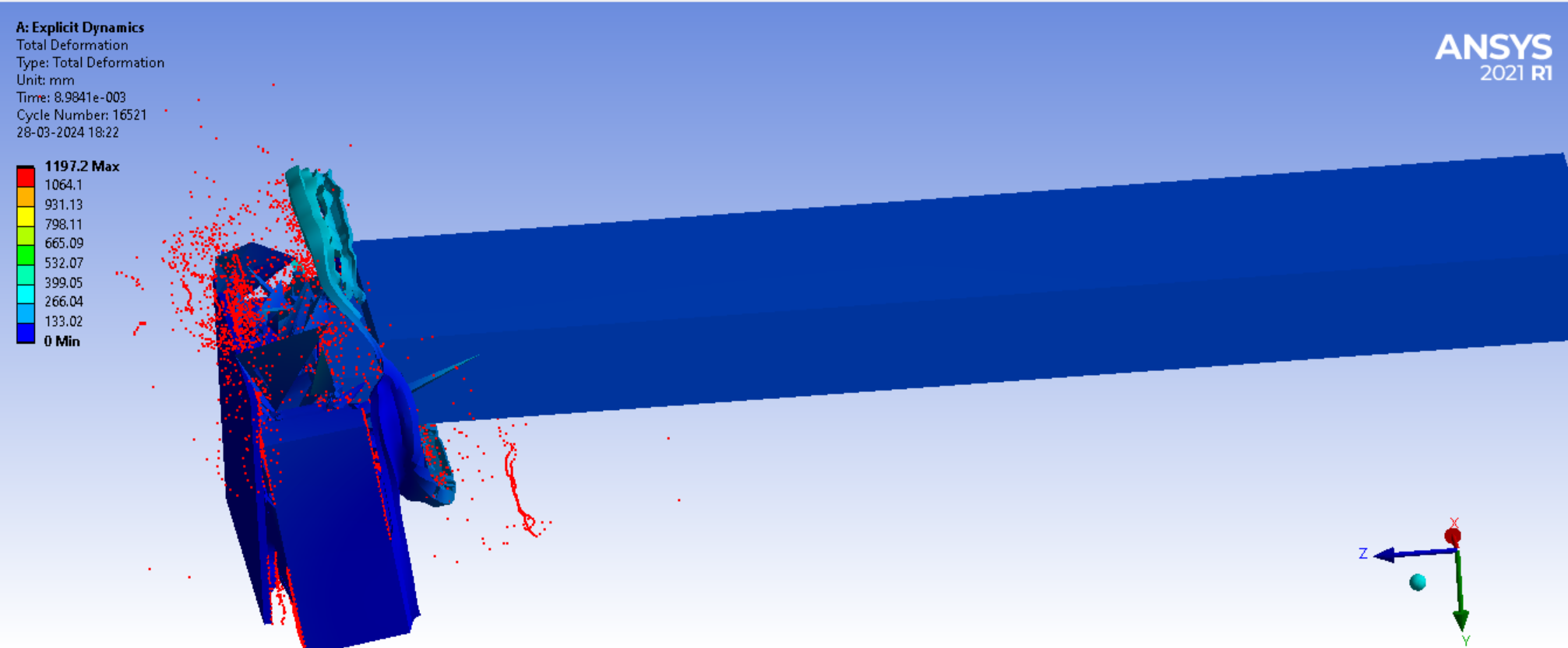
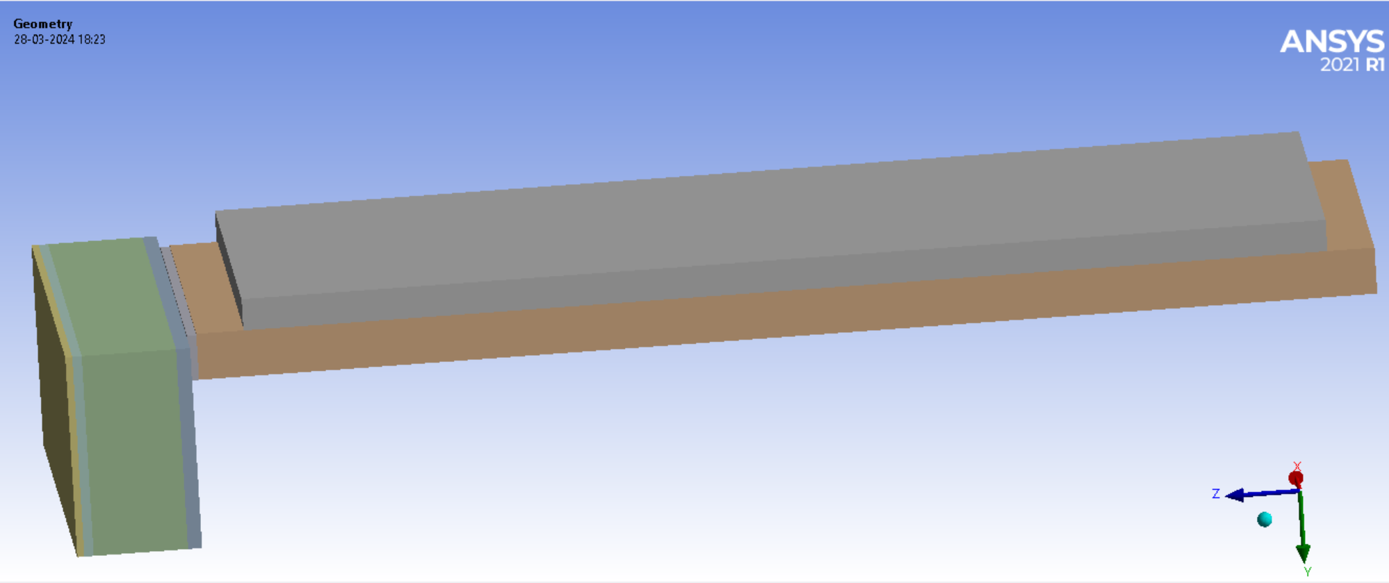
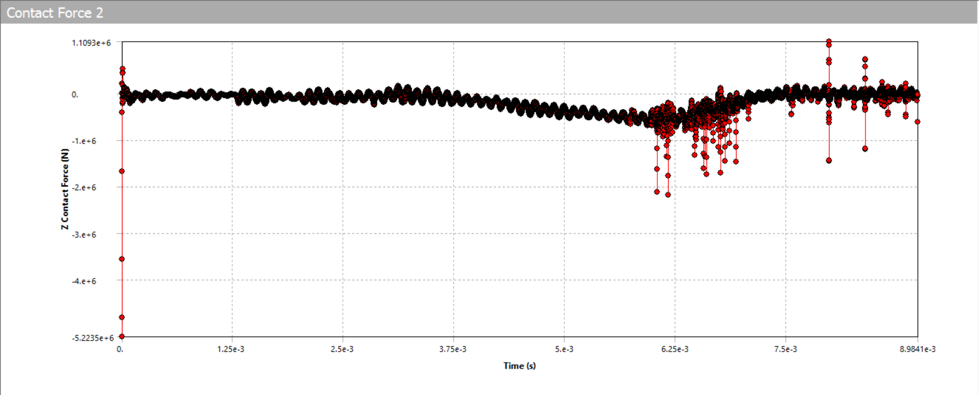
SubscriberHello Ansys Community,I am currently conducting an impact test for a stopper used to stop an aluminium vehicle moving with a velocity of 15m/s, utilizing the explicit dynamics module of Ansys. However, I am encountering challenges with either insufficient run time or difficulties in determining an appropriate time step, leading to undesired results. Specifically, my test involves a stopper made of rubber and foam with a steel plate attached at its end, being impacted by an aluminum vehicle moving at a velocity of 15m/s.Could anyone provide guidance on the exact process for conducting such an impact test in Ansys Explicit Dynamics? I am particularly interested in recommendations for setting up the simulation parameters, defining the contact and material properties, selecting appropriate time steps, and ensuring accurate and reliable results.Below are the results that we got from the simulations that were conducted. The graphs attached are for the contact forces on the steel plate of stopper and on the bumper attched to the aluminium vehicle. We intend to find the deformations and the contact forces for the stopper and the bumper of the vehicle to estimate the failure of the system.Any insights, tips, or best practices from experienced users would be greatly appreciated.Thank you in advance for your help. -
April 23, 2024 at 6:55 am
Ashish Khemka
Forum ModeratorHi,
Please refer to YouTube videos titled:
How to do the IMPACT test in ANSYS Workbench | EXPLICIT DYNAMICS
Ansys Tutorial - Impact On Chassis Using Explicit Dynamics Module(Crash Testing)
Regards,
Ashish Khemka
-
April 23, 2024 at 5:44 pm
Chris Quan
Ansys EmployeeThere are few things you need to check your model setup:
- How did you apply the Velocity of 15 m/s? This velocity should be applied using Initial Conditions -> Initial Velocity. The velocity drop of the vehicle indicates the amount of energy absorption by the rubber and foam materials. Constant Velocity Boundary Condition should not be used.
- You need to plot Energy Summary from Solution Information in Tree -> Solution Output to check how large the hourglass energy is. If hourglass energy is large comparing with Internal Energy, you need to refine mesh to reduce hourglass energy.
- Material rubber should use Hyperelastic material model. Material foam should use one of the porous EOS such as crushable foam to describe its behavior of volume change.
- Time step is automatically calculated by the program based upon CFL Stability Criterion. You cannot make it larger than the stability time step.
-
April 25, 2024 at 4:52 pm
be21b028
Subscriber1. I did apply the velocity of 15m/s using initial conditions.
2. Energy Summary was also plotted through solution output, but there was no change obtained in the graph.
3. Material rubber was used as the default material existing in Ansys library. How should I use hyperelastic material model?
4. Time step was calculated according to the materials used. The earlier simulations were made without providing the time step.
We have already tried doing these but still didn't get desired results. How could we check if the impact analysis that we did is accurate or not?
-
Viewing 3 reply threads
- The topic ‘Impact Analysis using Explicit Dynamics’ is closed to new replies.
Ansys Innovation Space


Trending discussions


Top Contributors


-
3477
-
1057
-
1051
-
945
-
912
Top Rated Tags


© 2025 Copyright ANSYS, Inc. All rights reserved.
Ansys does not support the usage of unauthorized Ansys software. Please visit www.ansys.com to obtain an official distribution.


