Ansys Assistant will be unavailable on the Learning Forum starting January 30. An upgraded version is coming soon. We apologize for any inconvenience and appreciate your patience. Stay tuned for updates.
Ansys Free Student Software

Ansys Free Student Software

Topics cover installation and configuration of our free student products.

Illegal External Terminal

    • J.MURPHY104
      Subscriber

      Hi,

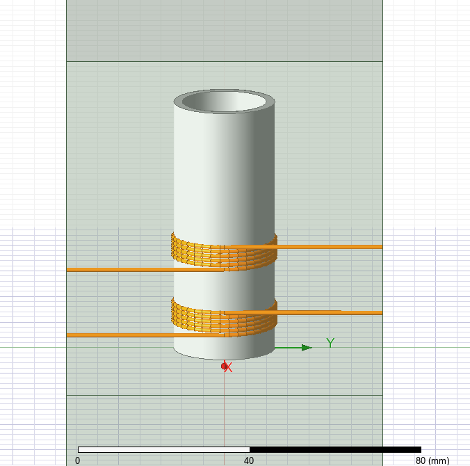
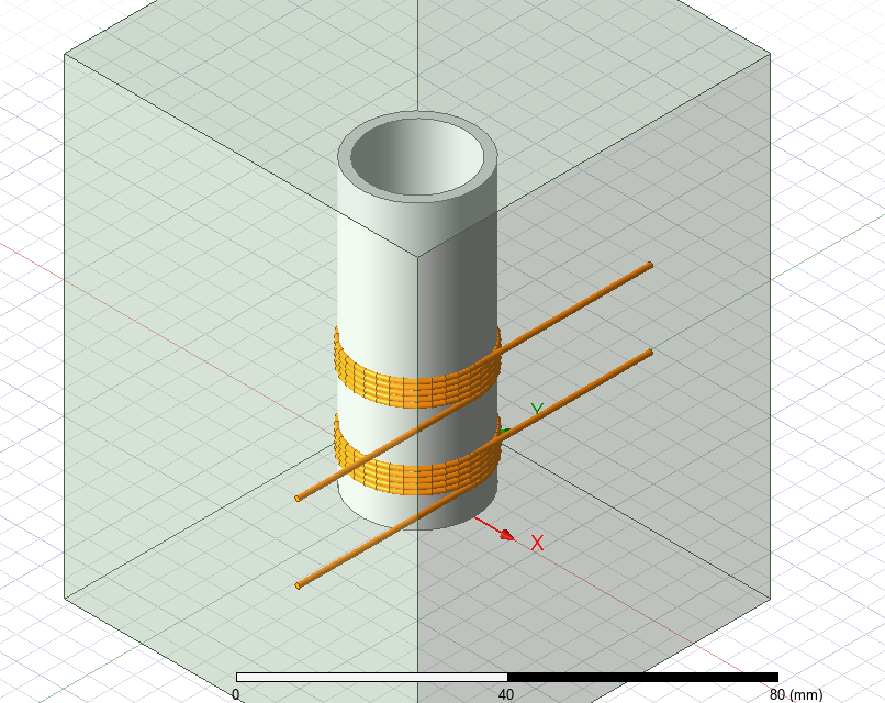
      I am getting the below error message. I am not sure what it means and what I have to do to resolve it. The external terminal borders the edge of the vacuum box in which I have put the design. Do I need to assign boundary conditions to the faces on which the coil terminals are ending? The current enters the coils on the left and exits on the right. The coils have the assigned coil terminal excitations and have been added to a winding, and the current direction is correct in both. Any insight would be greatly appreciated

      *Global - Messages
          [error] Illegal external terminal 'Current_In': An external terminal must border the edge of the problem region and coincides with the surface of a 3D object. (10:28:02 AM  Jan 15, 2025)
          [error] Illegal external terminal 'Current_Out': An external terminal must border the edge of the problem region and coincides with the surface of a 3D object. (10:28:02 AM  Jan 15, 2025)
          [error] Illegal external terminal 'Current_In1': An external terminal must border the edge of the problem region and coincides with the surface of a 3D object. (10:28:02 AM  Jan 15, 2025)
          [error] Illegal external terminal 'Current_Out1': An external terminal must border the edge of the problem region and coincides with the surface of a 3D object. (10:28:02 AM  Jan 15, 2025)

    • Ivonne Marti
      Ansys Employee

      Hi, 

      This error points to the aligment between the in/out current terminals and the Region surface. If you have created the Region drawing a box, is possible that you have a small gap (not easy to see). My advise is to create the Region going to Draw/Region, then select the "Pad individual directions" and ensure that in the Y direction (positive and negative) the percentage is zero.

      If you still have an error, please ensure that all the wires are long enough to touch the Region.

      I hope it helps

      Ivonne

      • J.MURPHY104
        Subscriber


        Hi Ivonne, thanks for the swift reply.

        I drew the copper wire very long then used the split command and selected split by face and chose the appropriate face on the Region box so that the wire is the exact length to interest with the Region box. I am still getting the same error message. Do I need to assign boundary conditions to the faces of the Region Box where the copper coil interacts for current in and current out?


Viewing 1 reply thread
  • You must be logged in to reply to this topic.
[bingo_chatbox]