

-
-
September 27, 2020 at 9:27 pm
shayanmehr
SubscriberI am simulating a foil in Ansys Fluent. When I used inflation for meshing, orthogonal quality hits under 0.1 in trailing edge, which is not desirable. Therefore, I used slice in trailing edge in order to fix this flaw.
However, the fluid domain is divided into two distinct fluid domains. I do not know how to define boundary conditions (inlet, outlet, walls, ...) after slicing which leads to two separate domains. Can you help me how to specify boundary conditions in this case?
September 27, 2020 at 10:53 pmpeteroznewman
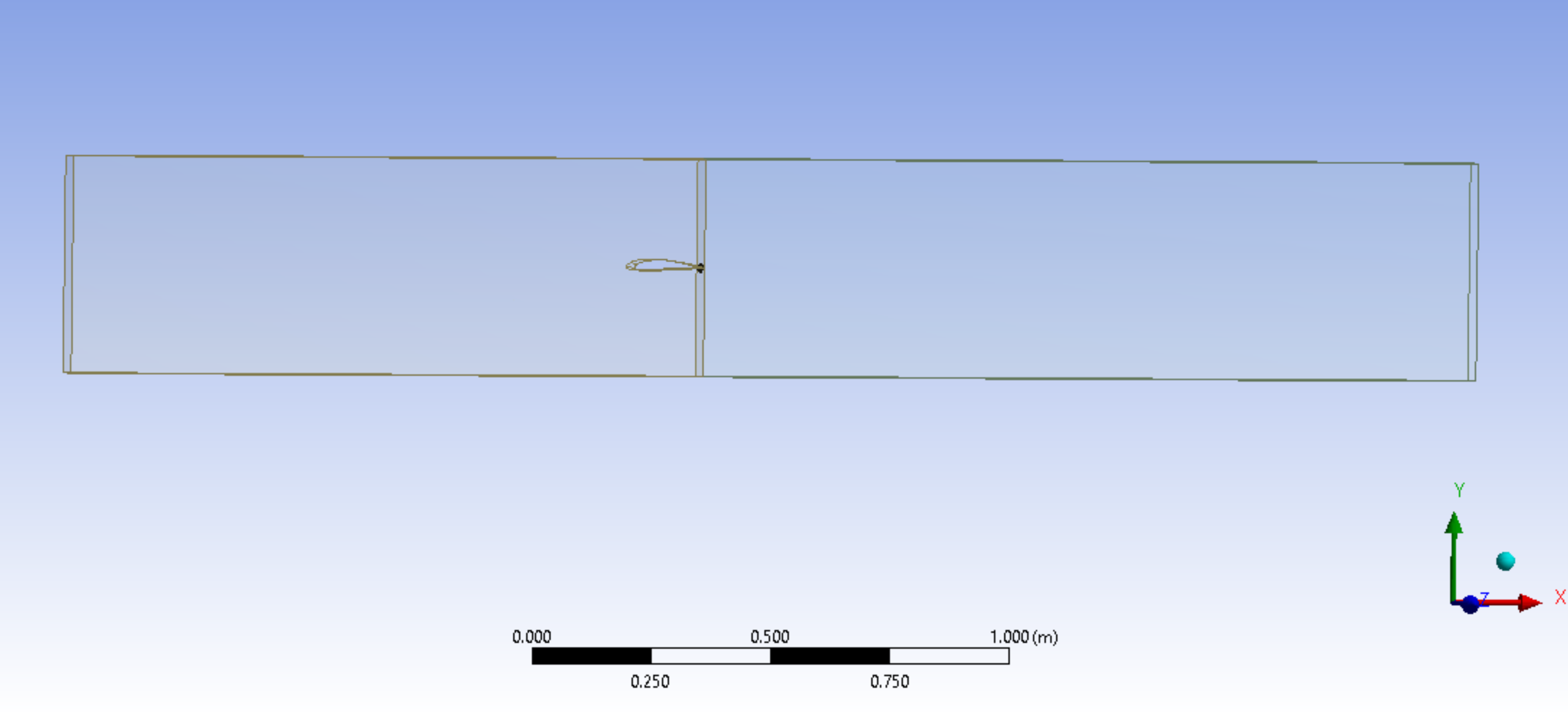
SubscriberSet the slice faces as Interior.nUse Shared Topology and delete any automatically generated contacts to minimize the interfaces that are created after slicing.nSeptember 28, 2020 at 1:28 pmSubscriberDear friend thank you for your response.nBut what are inlet, outlet and walls for this case?nI am confused how to set them because there are two separate domains (with the same fluid characteristics). Two domains can be seen in below picture, the left one which is in green color and the right one.n n
September 28, 2020 at 2:19 pmSubscriberThe inlet is the left face of the left domain, the outlet is the right face of the right solid.nI expect you should choose Walls for the top and bottom faces of the two domains.nUse Symmetry on the front and back faces of the two domains.nUse Interior for the faces that touch in the center.nSeptember 29, 2020 at 11:09 amSubscriberWhen I used Shared Topology, the orthogonal quality around sharp trailing edge decreased again. Is it ok if I don't use Shared Topology?.Also I have 2 cell zones after slicing, should I merge these 2 cell zones or no?n
n
September 28, 2020 at 2:19 pmSubscriberThe inlet is the left face of the left domain, the outlet is the right face of the right solid.nI expect you should choose Walls for the top and bottom faces of the two domains.nUse Symmetry on the front and back faces of the two domains.nUse Interior for the faces that touch in the center.nSeptember 29, 2020 at 11:09 amSubscriberWhen I used Shared Topology, the orthogonal quality around sharp trailing edge decreased again. Is it ok if I don't use Shared Topology?.Also I have 2 cell zones after slicing, should I merge these 2 cell zones or no?n n
September 29, 2020 at 12:39 pm
n
September 29, 2020 at 12:39 pmRob
Forum ModeratorIf you don't you'll get a mesh interface just as the flow gets interesting. If the cell size is near enough the same you should be OK, but it's not something I'd recommend. Please post some images of the mesh so we can see what's going on. nMultiple fluid domains are fine; I usually have a few, and they're regularly used for things like source terms and moving reference frames. nSeptember 29, 2020 at 2:52 pmSubscriberIt is my first mesh and as you can see, the mesh on the right side is not the same as the left side.n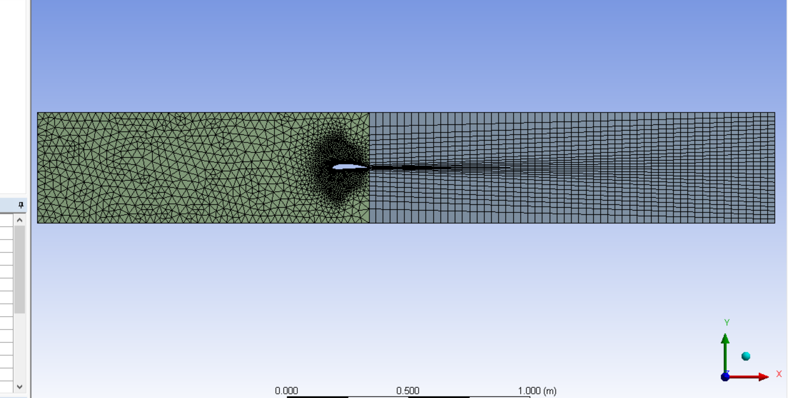 nso I used patch conforming method in order to make the mesh of the right side similar to the left side with tetrahedrons method:n
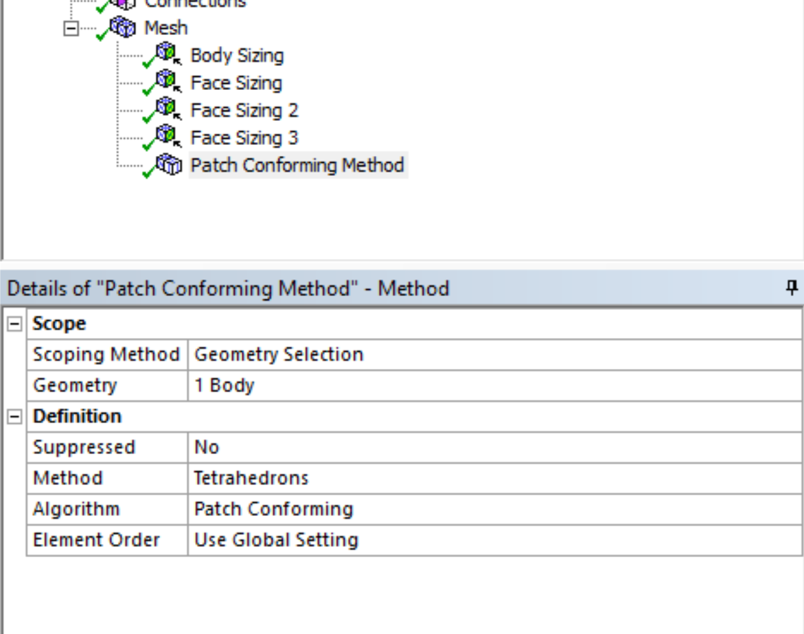
 nbut after that, bad mesh quality appears in the trailing edge as shown in below picture:n
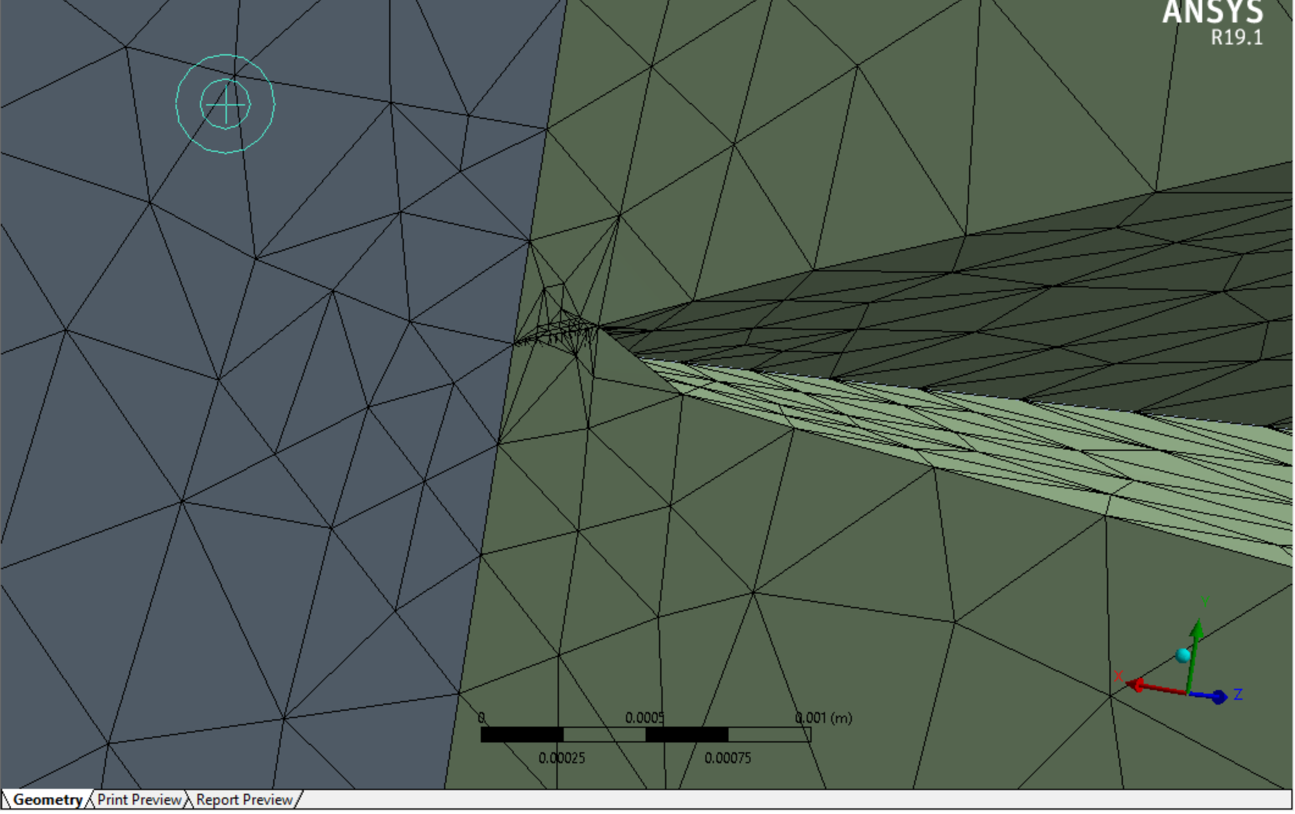
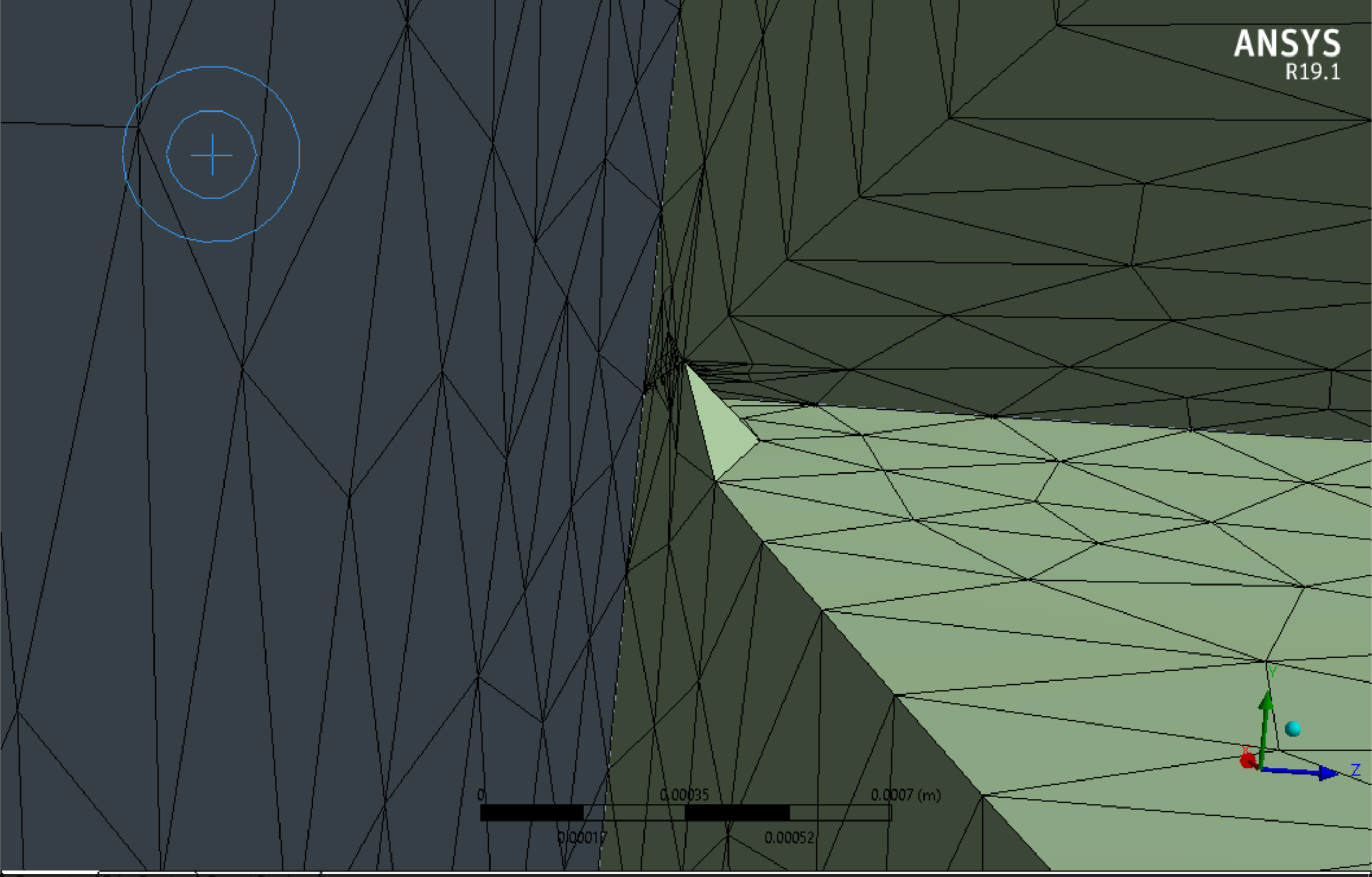 do you have any suggestion to solve this issue?n
September 30, 2020 at 9:39 amForum ModeratorTry a finer mesh towards the trailing edge. There's something very odd with the geometry in that area: what does the CAD look like?nOctober 13, 2020 at 12:15 amSubscriberCan you open the CAD file if I upload it?nOctober 13, 2020 at 12:42 am
do you have any suggestion to solve this issue?n
September 30, 2020 at 9:39 amForum ModeratorTry a finer mesh towards the trailing edge. There's something very odd with the geometry in that area: what does the CAD look like?nOctober 13, 2020 at 12:15 amSubscriberCan you open the CAD file if I upload it?nOctober 13, 2020 at 12:42 amKarthik Remella
AdministratorHello,nAs Ansys employees, we will not be able to download files attached on this Learning Forum. nPlease feel free to embed your screenshots directly in your post to highlight the features. As mentioned by Rob, I'd definitely try a finer mesh near the trailing edge. nThanks.nKarthiknViewing 9 reply threads- The topic ‘how to specify boundary conditions after slicing the fluid domain’ is closed to new replies.
Innovation Space Trending discussions
 Top Contributors
-
peteroznewman
 4773
4773 -
scabo
 1565
1565 -
Dennis Chen
 1386
1386 -
javat33489
 1242
1242 -
Shyam Prasad V Atri
1021
Top Rated Tags
© 2026 Copyright ANSYS, Inc. All rights reserved.
Ansys does not support the usage of unauthorized Ansys software. Please visit www.ansys.com to obtain an official distribution.
-


The Ansys Learning Forum is a public forum. You are prohibited from providing (i) information that is confidential to You, your employer, or any third party, (ii) Personal Data or individually identifiable health information, (iii) any information that is U.S. Government Classified, Controlled Unclassified Information, International Traffic in Arms Regulators (ITAR) or Export Administration Regulators (EAR) controlled or otherwise have been determined by the United States Government or by a foreign government to require protection against unauthorized disclosure for reasons of national security, or (iv) topics or information restricted by the People's Republic of China data protection and privacy laws.


