-
-
January 17, 2024 at 1:07 pm
ddol410
SubscriberHello, everyone.
I have constructed the phase-shifted bragg grating following the paper and compared two transmissions between my 3D FDTD result and the paper's result.
However, there are some differences between the two data, which show no peak and weak reflection intensity.
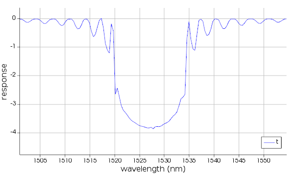
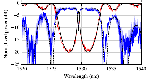
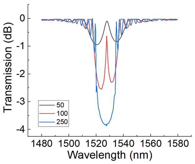
Although I match the object parameters with the paper's parameters, I think that the FDTD region and monitor/source location are the matter. But, when I reduced the number of periods to 50 and 100, it was weird to show a peak, unlike the conventional one which is 250.
So, let's look at my simulation setting.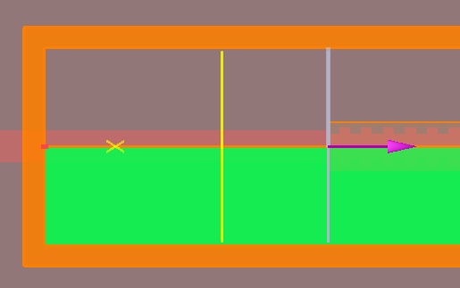
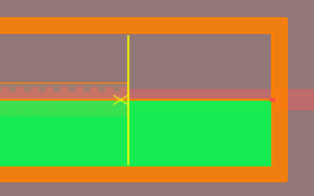
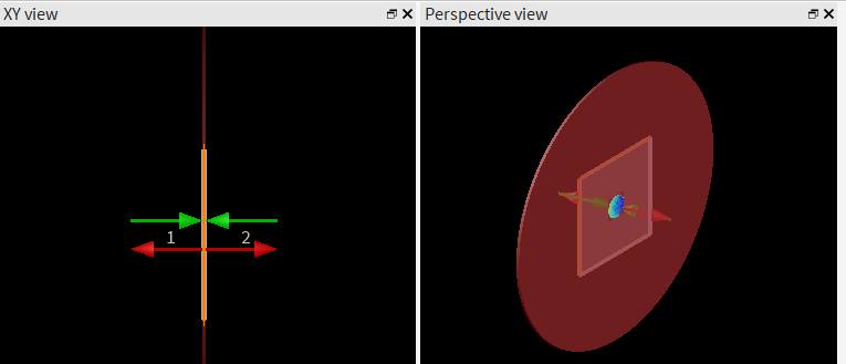
The first image is the input region and the other is the output region. I rerun the simulation by increasing the simulation time and mesh accuracy due to the simulation status 1.Is there any check point in my simulation setting?
I would be grateful if anyone could advise me on some solutions.
Thank you -
January 18, 2024 at 11:51 am
Dimitris Polyzos
Ansys EmployeeHello Kim,
thanks for your email.
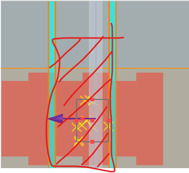
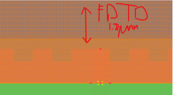
At the top of my head, I would recommend that FDTD region is not correctly set. As your current model is set up, and I assume that at x boundaries you set Bloch, the simulation considers that the region included in FDTD is repeatedly extended in -x and +x directions. I reckon that the way your model it is now, looks like a fabry-perot cavity with gratings as mirrors and teh input/output waveguide regions as cavity. If you want to simulate a Bragg grating spectrum and check you should include one period similar to the shaded region in picture below:
Could you let me know if you get a simulation status 1 or did you resolve it and now you obtain sim status 2? Also, it would help a lot if you could share with me the publication you base your simulation on.
Another option would be to include 100 periods in FDTD region and use -x and x BCs as PML, where you simulate only the structure included in FDTD BCs. That would take some time though as it need high simulation capacity. You could start with mesh accuracy 2.
I believe that you already had a look at these articles, however I mention them just in case you didn't:
Bragg-Grating-Initial-Design-with-FDTD
Bragg-Grating-full-device-simulation-with-EME
I hope I helped. Please let me know if you need further help with your model.
Kind regards
Dimitris
-
January 18, 2024 at 3:24 pm
ddol410
SubscriberThank you for your great interest, Dimitris.
I must have been grateful for your advice but, I'd like to design the phase-shifted Bragg grating with PML boundaries because it is a base step of my investigation leading to an expanded complex structure.
Is there any reason why the period structure could not be in PML boundaries?
Although I changed the simulation time and mesh level to various values, it still shows a status 1 or 3 and an inaccurate result compared with the paper result (Caverley, Michael, et al. "Silicon-on-insulator modulators using a quarter-wave phase-shifted Bragg grating." IEEE Photonics Technology Letters 27.22 (2015): 2331-2334.)
Kind regards
Kim -
January 19, 2024 at 11:20 am
Dimitris Polyzos
Ansys EmployeeHello Kim,
I might wrote my answer in a complicated way. Regarding your question, there is no restriction of including periodic structure in PML BCs. However, in order to consider your structure periodic you should use periodic BCs, especially at x direction in your case. What I meant in my previous email is that you can design a 100 or 400 period structure and apply PML BCs to all directions (x,y,z). This design will simulate a bragg grating of this specific number of periods, however it will take a long time to finish as it is not time effective. This article is quite informative regarding your question: PML-boundary-conditions-in-FDTD-and-MODE.
Regarding the simulation status you should get a simulation status of 2, as if not (1 or 3) means that the simulation is not completed. If the status of 1, it means that full simulation time has been reached but the energy has not dropped below the autoshutoff level. The spectrum calculated from Fourier analysis of the signal in time is therefore incorrect.If the simulation status is 3, it means that the simulation diverged. Please refer to this article for more information: Troubleshooting-diverging-simulations-in-FDTD
I hope I helped. Let me know if you need further assistance with your model.
Kind regards
Dimitris
-
January 21, 2024 at 6:02 am
ddol410
SubscriberHello, Dimitris.Thank you for your advice. It is helpful to be close to the accurate data.When I simulated the phase-shifted bragg grating of periods 50, and 100 with x,y, and z PML boundaries, it shows the peak wavelength and similar reflection range in the transmission data below. It is interesting that the difference is along with the length of periods.But, it still shows no peak in transmission data with 250 periods. But, all of the setting values are the same, just different from how many periods are on each side.I think the mesh size causes this problem, so I reduce the mesh size from x of 31nm, y of 25nm to x of 15.5nm, y of 10nm.Thank you.Kind regardsKim -
January 22, 2024 at 9:54 am
Dimitris Polyzos
Ansys EmployeeHello Kim,
I believe you are right. I would recommend to conduct a convergence test, checking the meshing versus reflection peak. This link, Convergence-testing-process-for-FDTD-simulations, will be very useful to have a look. Please let me know how it went and if you need further assistance.
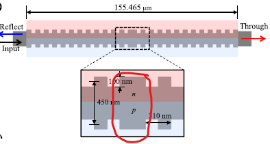
Also, the structure of the paper is not uniformly periodic along x axis (check red box in photo below) meaning that you supposed to have 2 peaks/valleys. Could you please send me a screenshot of your simulation regions of FDTD to check something?
I hope I helped. Please let me know if you need further assistance with your model.
Kind regards
Dimitris
-
January 25, 2024 at 5:58 am
ddol410
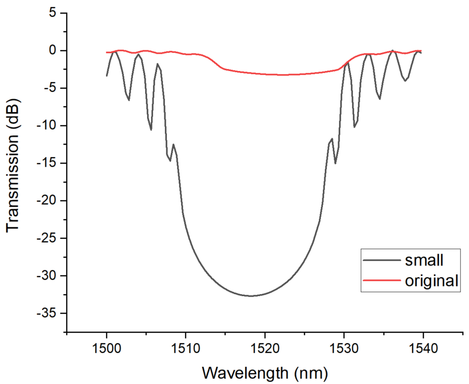
SubscriberHello, Dimitris.I'm trying to conduct the convergence test along with the mesh size.It was interesting that the reflection intensity recorded a deep valley when the y of mesh size decreased to 5nm from 25nm.In the theory of bragg grating, the corrugation width influences the reflection due to the coupling coefficient. And I supposed that decreasing x mesh means a detail propagating light in structure leading to a peak conclusively.But the result makes me stuffy because it still doesn't show a resonance peak and lower reflection again in my simulation. In that running, I set the mesh size to 7.75nm of x mesh and 5nm of y mesh. One thing that I am concerned about is the simulation status of 3, and the simulation time is 5000fs. But, it requires much time to run the simulationThe below screenshots show the region of the phase-shifted grating waveguide and FDTD divided by the input, phase-shifted region, and output. The input and output parts are posted on the upper page.I think there are no problems with the physical setting.
Thank you for your great interest again.Kind regards
Dimitris
-
January 25, 2024 at 12:24 pm
Dimitris Polyzos
Ansys EmployeeHello Kim,
thanks for your reply. I believe that I shared this link Troubleshooting-diverging-simulations-in-FDTD again, however I would recommend to have a look to troubleshoot the simulation status 3, as it seems that your simulation diverges, leading to non accurate results. I cannot understand how you set your FDTD simulation regions in this picture. COuld you please share a [icture similar to the one below on the right?
Kind regards
Dimitris
-
- The topic ‘How to simulate the phase-shifted bragg grating in 3D FDTD?’ is closed to new replies.


-
4618
-
1530
-
1386
-
1210
-
1021

© 2025 Copyright ANSYS, Inc. All rights reserved.

