Ansys Assistant will be unavailable on the Learning Forum starting January 30. An upgraded version is coming soon. We apologize for any inconvenience and appreciate your patience. Stay tuned for updates.
General Mechanical

General Mechanical

Topics related to Mechanical Enterprise, Motion, Additive Print and more.

How to simulate slip between components due to rotational speed

    • Rashi
      Subscriber


      Hi, 


      Above image represent what I'm going to simulate. Shaft (gray) consists of two other components. The component in "Green" act as a sleeve which is used to assemble the "dark gray" part to the shaft using interference fit. 


      Whole assembly rotates at around 150,000 rpm.


      I need to find the optimum interference fit where there will be no slip occurs between the shaft and other components. All the contact surfaces are given frictional contacts.


      How can I simulate the following?


      Here's what I did up-to now.


      My idea is to rotate only the "shaft" which will force the other components to rotate if the interference is sufficient. As far as I know when using "static structural" simulation the rotational speed is applied as a inertia force. So using static structural will not simulate the physical condition correctly. 


      So I selected transient structural, but my issue is if I give "rotational speed" boundary condition will the effect only be applied as inertia load?
      If so how can I specify the boundary condition where the shaft will physically rotate?


      Furthermore, does the geometry have to be analysed in full 3d form? or can I use simplification such as cyclic symmetry or axi-symmetry? 


      Also since the rotational speed is very high what is the best method to give the time step settings to achieve convergence? 


      Thank you.


      Best Regards,


      Rashiga


    • peteroznewman
      Subscriber

      Hi Rashiga,


      I would build a Static Structural model that has two (or more) steps. In the first step, the designed-in interference in the frictional contact is resolved to create an initial contact pressure for a stationary shaft, with the stretch and compression of the layers at each diameter computed at the end of step 1.


      In the second step, the rotational velocity and rotational acceleration is applied. Each material layer has its own density and Young's Modulus that makes it stretch to come to equilibrium at the specified rotational velocity.


      The contact pressure can be examined at Step 2 to determine if an adequate amount of pressure is present to prevent slippage, given the known coefficients of friction between the various layers and the rotational acceleration. You haven't specified the rotational acceleration. It is only under rotational acceleration that there is a torque on the layers that would induce slipping.


      If you have a rotational velocity and acceleration profile, you could make several steps along that profile and have the acceleration included along with the velocity. The maximum rotational acceleration would be at the start of a spin-up or slow-down profile. At spin-up, the rotational velocity is lowest, the contact pressure is highest, so the propensity to slip is lowest. On the other hand, putting on the brakes to slow down from maximum velocity is when the contact pressure is lowest, so the propensity to slip is highest.


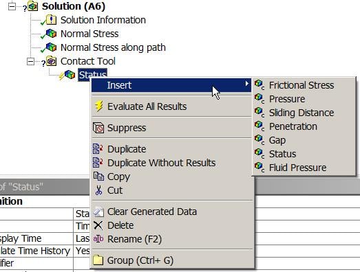
      In the contact results, you can see directly the tangential forces in the contact elements and determine the margin to slipping. If it does slip, the solution will fail to converge, which is okay since that is an unacceptable design and you need a higher contact pressure.


      Regards, Peter

    • Rashi
      Subscriber

      Dear Mr. Peter,


      Thank you for your suggestion and I did exactly as you mentioned. But I have two questions, 


      1. Does the tangential force visualized using a "probe>reaction force"?  also do I have to define a cylindrical coordinate system to get the tangential force?


      2. I did the simulation with "Large displacement" on and off and the contact pressure between the shaft and the middle component had a large difference with each setting. Since this is a non linear contact simulation is it better to use the result with "large displacement" on?


      3. Also in transient simulation does the time step corresponds to the actual time scale in real world? If its so if we give a velocity as a ramp does ansys think it as a constant acceleration input? 


      Thanks.


    • peteroznewman
      Subscriber

      Dear Rashiga,


      1. It would be very useful to define a cylindrical coordinate system. I think the tangential force is relative to the normal of the contact element so it might not need a cylindrical coordinate system. See if you get a different result. I haven't examined it myself.


      2. Yes, you want Large displacement On for Static Structural. Without it, the expansion of the sleeve will be much larger than reality.


      3. Yes, time in a Transient Dynamics is real time and so the ramp up of velocity represents a constant acceleration. The acceleration profile from an electric motor is not going to be constant from zero to maximum velocity and the profile is going to be different again stopping.


      Regards, Peter

    • Rashi
      Subscriber

      Dear Mr. Peter, 


      In the assembly I tried to apply the rotational velocity and rotational acceleration to a single body. But I was unable to do so. I was only able to apply both condition to the whole assembly.


      What is the reason for that?


      Best Regards,


      Rashiga


    • peteroznewman
      Subscriber

      Dear Rashi,


      The entire shaft has the same rotational velocity and acceleration in a Static Structural model because it is an Inertial load being applied to all mass in the model.


      Regards, Peter

    • Rashi
      Subscriber

      Dear Mr. Peter,


      Sorry for asking such a trivial question before.


      We can use the contact status option to determine the status of the contact? But I want to know if the status can be seen according to particular direction, as per this example contact sliding in axial and tangential direction?


      Thank you.


      Best Regards,


      Rashiga


    • peteroznewman
      Subscriber

      Dear Rashiga


      Here are the results available in the Contact Tool.


      However, you can plot the directional displacement of each face of the two parts to look at the differential displacement.


      Regards, Peter

Viewing 7 reply threads
  • The topic ‘How to simulate slip between components due to rotational speed’ is closed to new replies.
[bingo_chatbox]