TAGGED: interconnect, signal-to-noise-ratio
-
-
January 5, 2025 at 9:50 pm
m.belchovski
SubscriberDear,
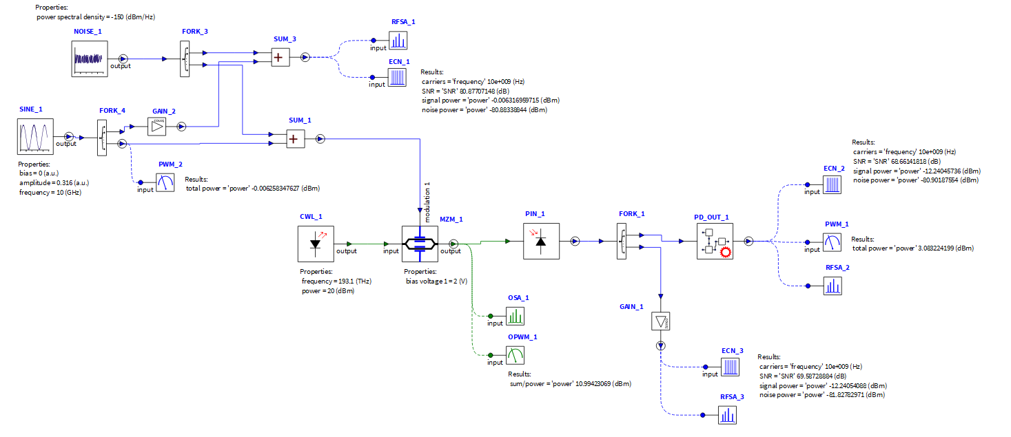
I am trying to simulate, and estimate from the simulation the noise figure of a simple optical link (as shown in the figure). It is a bit elaborate to explain here what I want to do with the circuit, but in short: I have an RF signal and a certain noise power at the input that determines my SNR_in. At the output I recover the RF signal (the power of the signal is correct), however the noise PSD or noise floor does not seem correct. So my SNR_out estimation is not okay, and the overall NF is not correct. Do you have any suggestions how I can get more accurate results for the noise PSD or noise floor to calculate the output SNR? I compare my simulation results with exact theoretical results for this kind of link. Please, if you need further information let me know. Thank a lot!
-
January 6, 2025 at 5:19 pm
Devika Padmakumar Nair
Ansys EmployeeHello,
More information on the noise figure calculation which you might find useful:
Optical Amplifier (AMP) – INTERCONNECT Element – Ansys Optics
Also, have a look at the Frequency Noise Analyzer for Interconnect Optical Frequency Noise Spectrum Analyzer (OFNSA) – INTERCONNECT Element – Ansys Optics
Hope this helps.
Let me know if you require futher assistance.
Thank you
-
- You must be logged in to reply to this topic.


-
3367
-
1050
-
1047
-
886
-
837

© 2025 Copyright ANSYS, Inc. All rights reserved.


