-
-
August 4, 2021 at 5:28 am
ashishsv99
SubscriberAugust 4, 2021 at 12:29 pmpeteroznewman
SubscriberWhat direction is Z axis pointing?
Use a Static Structural model to allow gravity to compress the structure.
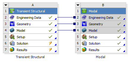
Link the Solution cell of the Static Structural model to the Setup cell of a Modal analysis. This will compute the prestressed natural frequencies.
Link the Solution cell of the Modal analysis to the Setup cell of a Harmonic Response analysis. This will give you the steady state solution and is much more efficient that a transient analysis.
That will allow a base excitation to occur where you can sweep the frequency w over an input range and find out the response of the isolated object.
Note that this is a Linear Analysis and is only valid for small deflections.
August 4, 2021 at 1:10 pmpeteroznewman
SubscriberAugust 5, 2021 at 2:51 amashishsv99
SubscriberHi, I am sorry about the spam posts.
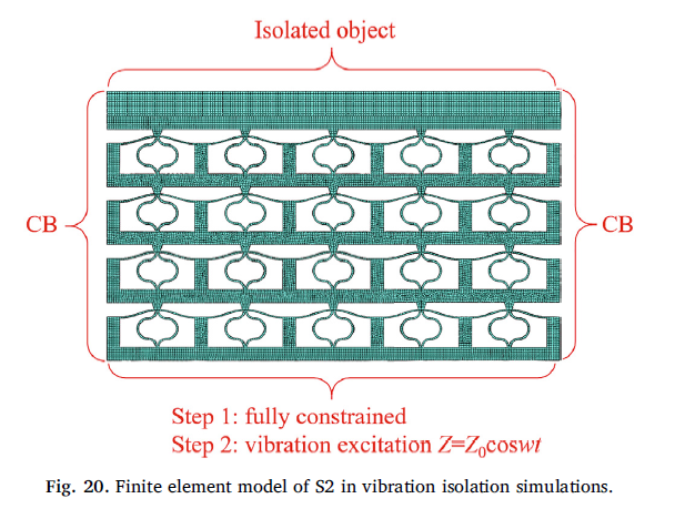
Here, Z is the vertical direction here where the isolated object is made to move downward because of gravity and the base is excited to vibrate up and down.
Also, I was thinking if it is okay to provide a constant force over the top surface rather than placing the isolated object?
I haven't used harmonic response before so if you could tell me as to which parameters I will have to take care of in the analysis settings, like how do I figure out the frequency range.
And for the base excitation, I should first add a displacement to the bottom surface and then turn on base excitation and in the magnitude, I should give Zo cos(wt), am I correct? Here Zo is 5mm. But what value of w should I be using for this?
August 5, 2021 at 5:42 amashishsv99
SubscriberAugust 5, 2021 at 5:52 amashishsv99
SubscriberAlso, my material properties are hyperelastic, I have given tensile test data as input and then done curve fitting using Mooney-Rivlin 5 parameter.
August 5, 2021 at 11:05 ampeteroznewman
SubscriberOkay, the last point that you have a hyperelastic material excludes the use of everything I was saying because that is a nonlinear material.
Take the free courses offered on this site to learn about Harmonic Response the next time you have linear elastic materials experiencing small displacements of vibration.
August 5, 2021 at 11:19 amashishsv99
SubscriberAlright I will check it out, but as for this problem with hyperelastic material, what should I do to simulate this type of analysis.
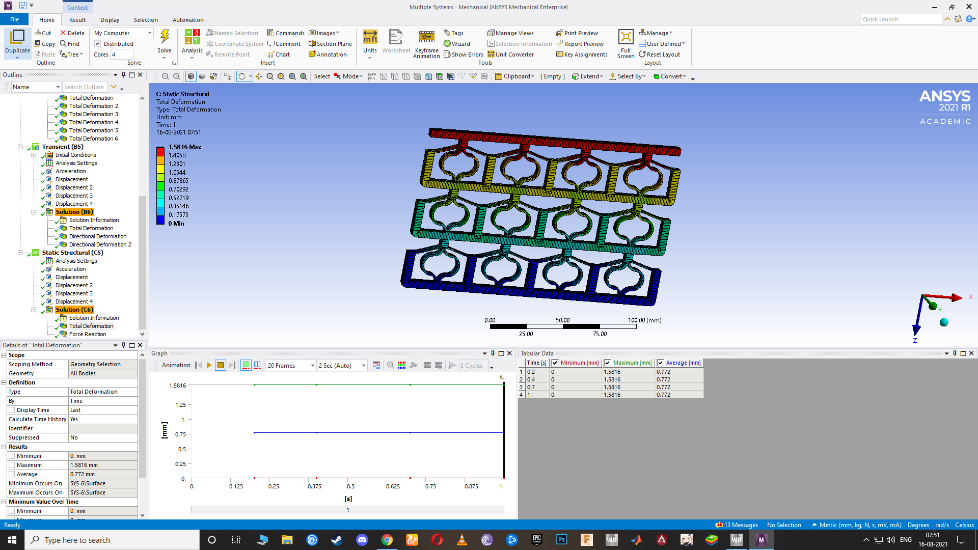
I tried Modal+transient and did not get the correct results.
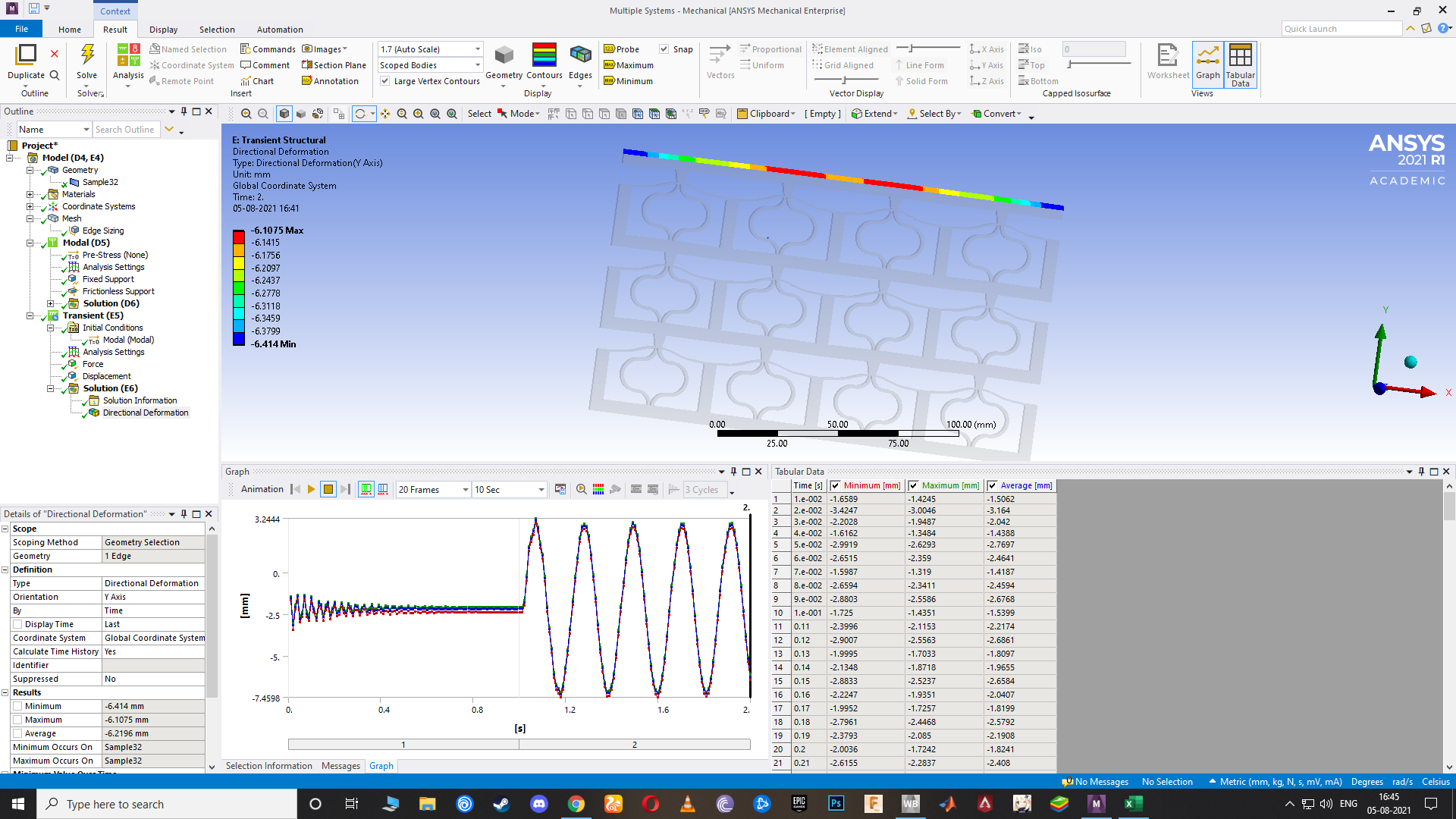
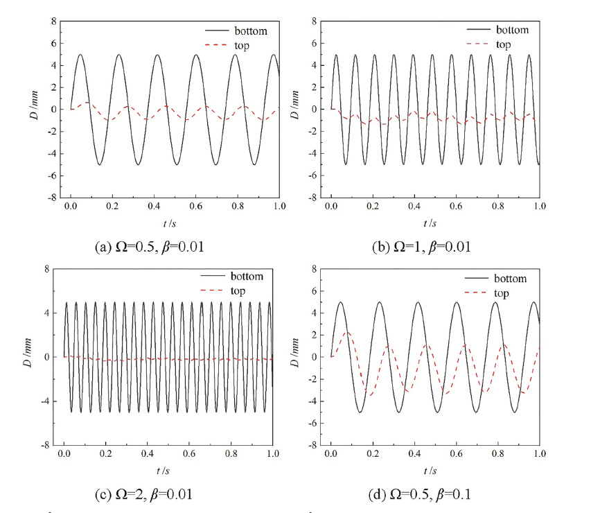
Here my step 2 was given base excitation of 5mm amplitude and the output is pretty much having the same amplitude, but in reality, it should dampen out those vibrations and have a small amplitude as the other graph shown previously of disp vs time.
So what should I be doing for it? I will check out the harmonic response tutorials and the course from here as of today and try to understand it.
August 5, 2021 at 11:36 ampeteroznewman
SubscriberI expect the Modal analysis would give an error due to the hyperelastic material model. If you got modes out, maybe you don't have a hyperelastic material model assigned to the body?
You should just run Transient Structural as Erik suggested in this thread:
/forum/discussion/30332/how-to-perform-two-step-dynamic-analysis#latest
In the Step controls, turn off Time Integration to compute the static deflection of the structure during step 1, while the base is held with zero displacement.
In Step 2, turn on Time integration, but don't apply any motion of the base. This is needed to avoid assigning an initial velocity to the top mass, which would be the distance moved divided by the duration of step 1.
In Step 3, begin the motion of the base.
August 5, 2021 at 12:15 pmashishsv99
SubscriberYes for the modal analysis I did get an error, so instead I used an elastic model since my strain values that occur when load being applied is very small, the material almost behaves linearly, so I just made the assumption and tried it out.
Alright I will try performing the transient analysis as you said and if any doubts I will get back.
Thank you so much.
August 5, 2021 at 3:11 pmpeteroznewman
SubscriberWell if you have switched to a linear material, then you can do the Harmonic Response method, it is much less work, but a 5 mm amplitude seems way more than a small displacement.
August 6, 2021 at 2:08 amashishsv99
SubscriberI had a doubt if I should constrain the top surface of the isolated object because when I did the simulation, instead of the vibration damping out the isolated object, it is rather moving with the same motion as the base. Or am I doing something wrong because of which I am not getting the correct output?
August 6, 2021 at 2:12 ampeteroznewman
SubscriberYou should not constrain the top surface of the isolated object. That is just there to provide mass.
August 6, 2021 at 2:13 amashishsv99
SubscriberOkay so just to make things clear, I will share the pdf to the research paper here, if you could go through it and explain to me things that I have to do in order to get my results and to make sure I am not feeding in garbage inputs. This is really important to me as I am currently working as an intern and they have asked me to reproduce the results from the paper to get my internship certificate. I would really really appreciate your help with this. They have done the analysis using abaqus and I am trying to do the same using ANSYS.
August 6, 2021 at 2:16 amashishsv99
SubscriberI am really sorry for being such a bother since I am fairly new to this field and at using this software yet I am trying to rush things just to get the results. For the time being, I will prioritize getting the results fast but also will take my time later to learn things more in-depth and understand the basics better.
August 6, 2021 at 5:45 amashishsv99
SubscriberJust letting me know the steps that I've to follow for this analysis would be of great help.
Also, if you could try it out by yourself and see if it works just fine and sharing it would be helpful. I will watch that and learn how you are doing it. I will attach the model file here.
It is a 2D model of it.
August 6, 2021 at 5:48 amashishsv99
Subscriberisolated object is not in the design though.
August 6, 2021 at 9:20 amashishsv99
SubscriberHi, I have tried the 3 step transient analysis as suggested by you, I will share the google drive link to my Ansys files, please if you could check it out and let me know of my mistakes in it and tell me what changes I've to make, that'll be great.
https://drive.google.com/drive/folders/14DwSzFnR2-vvIvg9foi8eo-rQ8QRnhxS?usp=sharing
August 6, 2021 at 11:42 ampeteroznewman
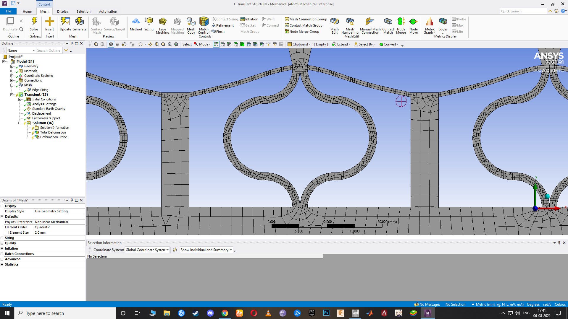
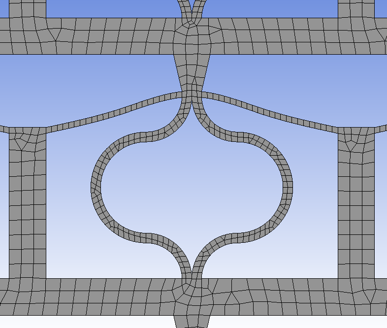
SubscriberI have started to look at your 2D model. First observation: you must have at least 2 quadratic or 4 linear elements across the width of any member that will see bending deformation. This mesh has only 1 element, which is insufficient. I will continue to investigate over the next 3 days and post new information as I find it.
 August 6, 2021 at 12:01 pm
ashishsv99
SubscriberAlright thank you so much for the help. I will make the changes.
August 6, 2021 at 12:12 pmAugust 6, 2021 at 4:26 pmashishsv99
SubscriberIt is my time to sleep, so please do send all the changes that I gotta make and I will check it out and do that in the morning.
August 7, 2021 at 2:32 amashishsv99
SubscriberAlso, the problem with my software is that it is a student edition, so there is a limit to the number of elements my model can have.
If we could try to finish this by today or tomorrow, that'll be great since Monday is my deadline for the progress report.
August 7, 2021 at 5:08 amashishsv99
SubscriberI have other related doubts with static analysis too which I will ask later. Basically I tried static analysis to get F vs D graph while base is fixed and the top surface is displaced in steps.
I tried it for both the whole metastructure as well as unit cell, I should get a non linear curve with a little flat region in the middle, which I got correctly for the metastructure but not for the unit cell.
 This was my graph for the metastructure
 And this is for unit cell, which is wrong. I used the same procedure for both during the analysis.
August 7, 2021 at 3:21 pmpeteroznewman
SubscriberThe two graphs in your last post are not plotted on the same axes, one is F vs D, the other is U2 vs what? Please label axes and include units. Also, the metastructure has 3 layers of unit cells so if you displace that 30 mm, you should compare that with a unit cell displaced 10 mm.
I have a post that lists recommendations for models that use hyperelastic materials. You need to follow that advice if you continue to use 2D Plate elements. This is not necessary if you use 3D Shell elements.
I tried 2 quadratic elements through the thickness and it did not perform well. I had to do some slicing of the domain in order to get pieces what would be easily meshed. The image below has 6 linear elements through the thickness.
 Another approach to this model is to abandon the 2D meshing of a surface and replace the entire model with beam elements on line bodies. That would eliminate any concern about how many elements are through the thickness and it would reduce the node count to a very low number which would make the transient solution compute much more quickly. I built the mesh shown below, then learned that Beam188 elements do not support hyperelastic material models. So if you can use linear elastic materials, you could use this approach.
 Next I extruded the line bodies into sheet bodies 10 mm wide. Shell elements increase the node count by 4 times over the line bodies above, but is still a lot fewer nodes than the 2D Plate elements.

 August 7, 2021 at 4:39 pm
ashishsv99
SubscriberOkay, I am still trying to understand what you have done here. Also, my U2 graph was Force on x-axis vs number of steps on y-axis where each step was 0.1 mm disp.
August 7, 2021 at 4:54 pmashishsv99
SubscriberThank you so much for the video, that made it easier to understand this.
August 7, 2021 at 5:05 pmashishsv99
SubscriberHow are the face sheets /surfaces created? and how do they act as 3D objects?
August 7, 2021 at 5:08 pmashishsv99
SubscriberAnd the force reaction is considered for both the fixed supports and not just the bottom fixture. Why is that?
August 7, 2021 at 6:20 pmpeteroznewman
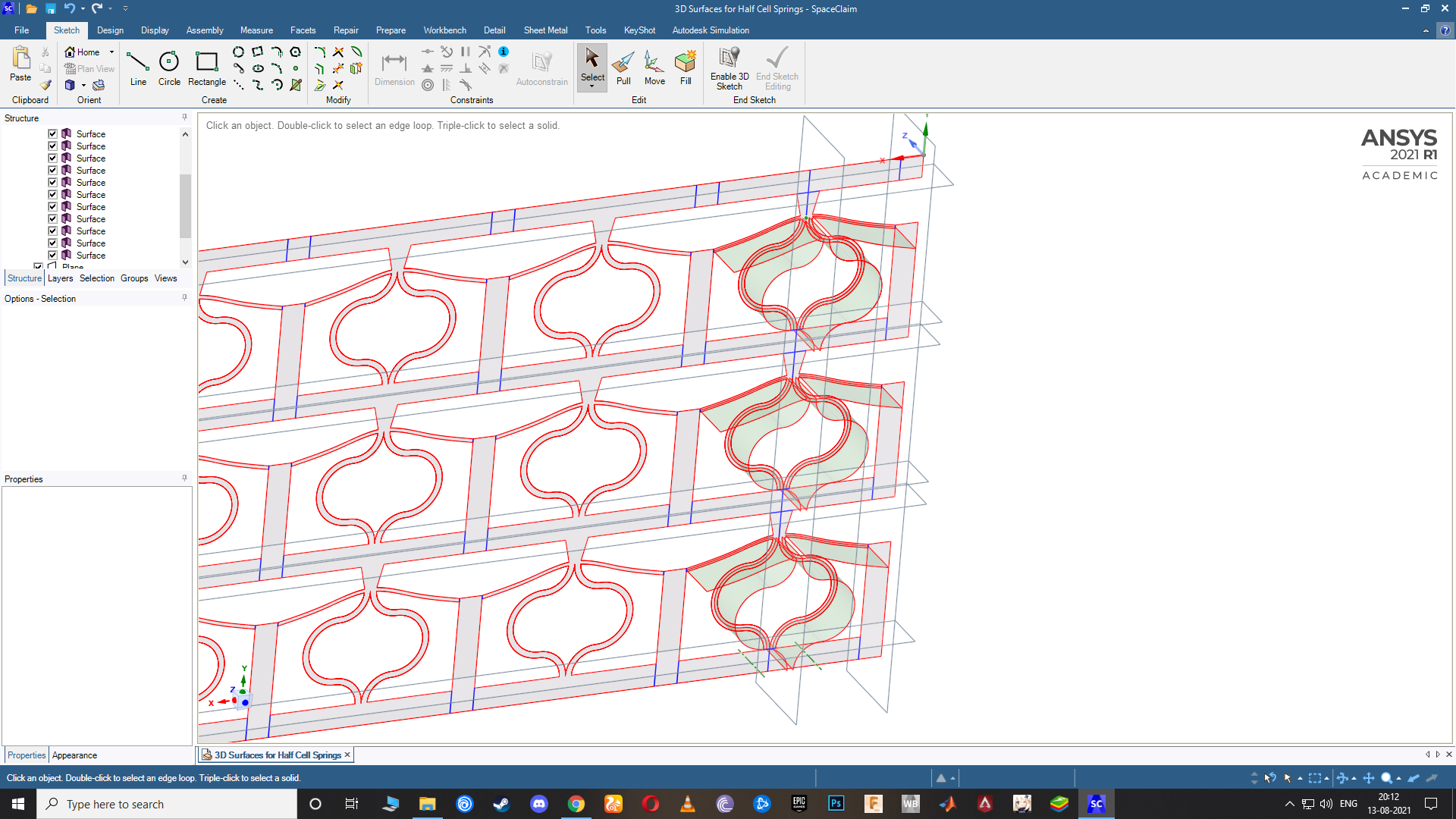
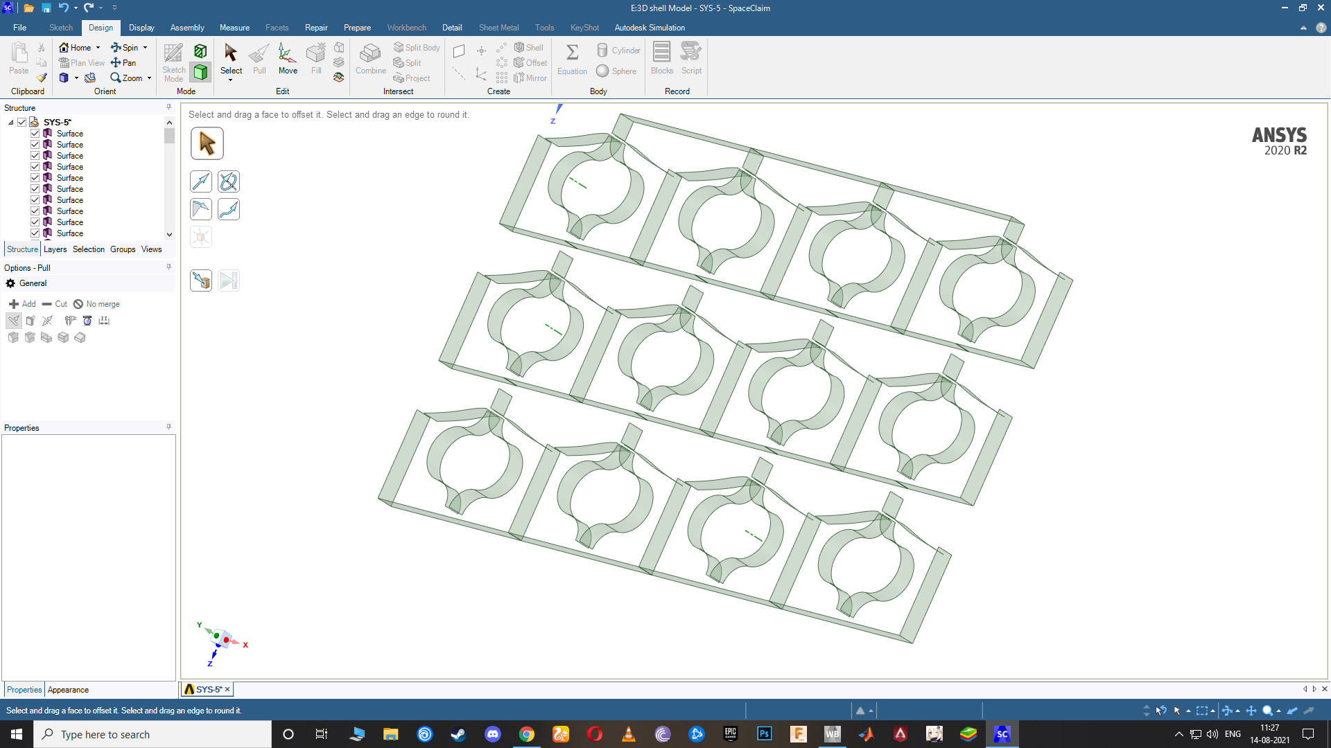
SubscriberIn SpaceClaim, I offset the edges of the 2D planar surface to get curves on the centerline of each flexure. Then I used the Pull tool to pull the curves along the Z axis to create the surfaces. In Mechanical, each surface is assigned a material and a thickness. The 3D surfaces are meshed with Shell elements in a 3D analysis. Shell elements have equations that compute bending of the shell.
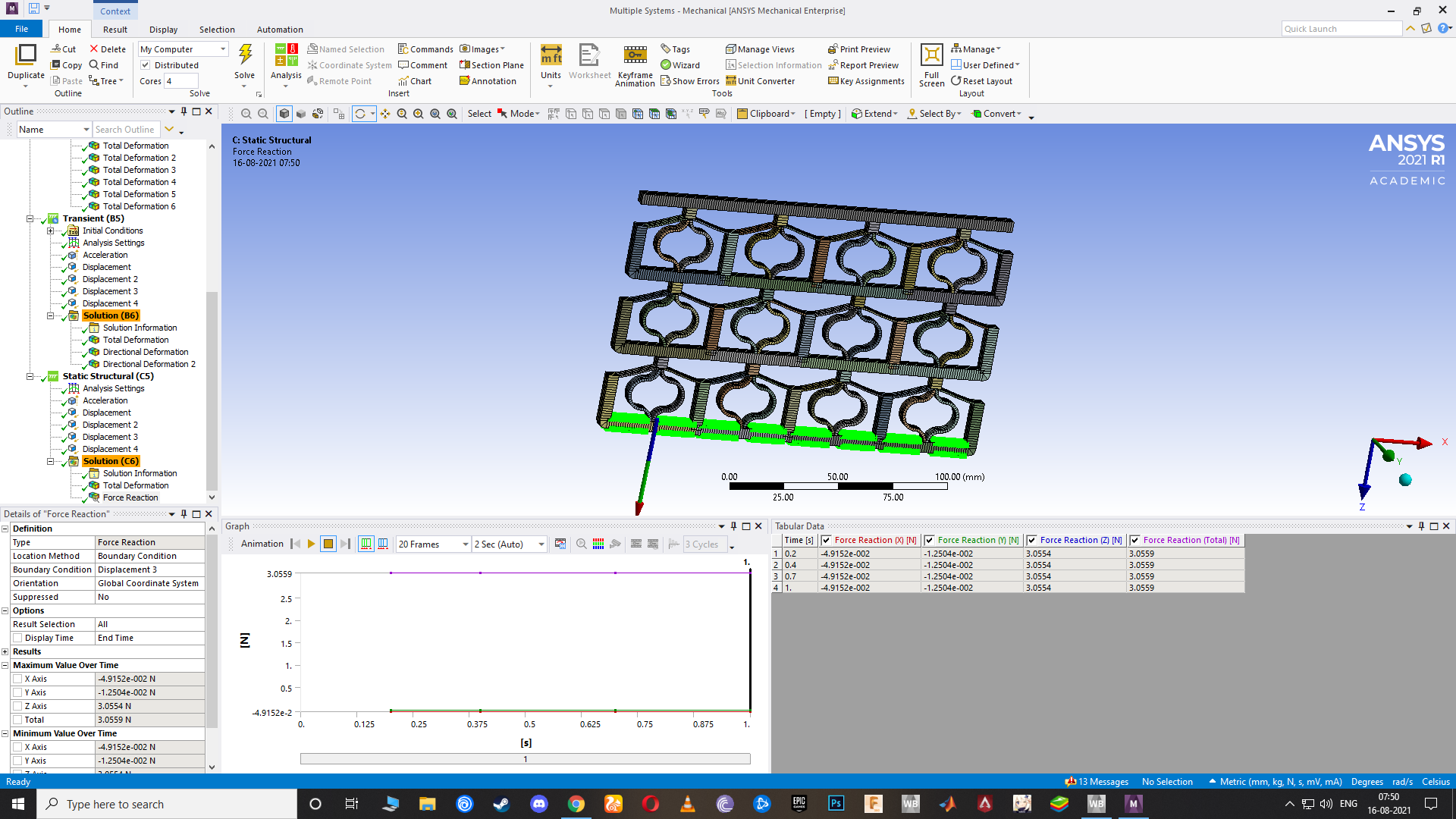
The Force Reaction is for the Remote Displacement at the top. The force is the Y component only so represents the vertical force. You could multiply the force by 2 to include the other half of the cell that was not in the model.
August 8, 2021 at 12:19 pmashishsv99
SubscriberAlright done, I understood it. One doubt though as to why did my 3d or 2d model not work even with a good amount of meshing for the thin beams?
Also, just the transient analysis remains right? If it can be done by today or tomorrow, that'll be great so as I can also try it out myself once and learn what all is done for it. Submissions are near too.
August 8, 2021 at 12:20 pmashishsv99
SubscriberPlease look at my transient model and what can be Changed to make it correct?
August 8, 2021 at 1:44 pmpeteroznewman
SubscriberDo you have a new 3D shell model to use for Transient Dynamics that I can look at? If so, please attach an archive.
If you will no longer be using the 2D plane stress model, I don't want to spend time on that.
August 8, 2021 at 2:05 pmashishsv99
SubscriberNo, I do not have a 3D shell model of it. I have only tried it out with 3D solid and 2D planar models until now. I wasn't sure as to how I could work with the shell model.
August 8, 2021 at 3:18 pmpeteroznewman
SubscriberI ran the top surface down using a Displacement BC, without gravity, in order to plot the force-displacement graph.
It looks like you adjusted the mass of the supported object and the frame itself in order to put this mass on the flat portion of the force-displacement graph.
The deflection due to gravity is working as it should.
 August 8, 2021 at 3:45 pm
ashishsv99
SubscriberYes for the F vs D results I did static analysis without gravity and only giving displacement to the top surface with bottom fixed, tried this using both 3D and 2D models and got pretty accurate results.
For the mass, it is said that the compression during the first step should be almost equal to the force value where it is almost flat as seen from the F vs D graph. Or we can say that there should be around 15 mm of displacement for the whole metastructure or around 3.2 N force being applied for this to occur. For that, I got a calculated mass of 0.3262Kg.
August 8, 2021 at 3:51 pmashishsv99
Subscriberwhat I did was just use the structural steel material and changed its density to match the 3.2N force that it should be applying
August 8, 2021 at 8:25 pmpeteroznewman
SubscriberHere is the input to the Transient Dynamics model. I stopped the solution at 2.4 seconds to check the progress.
 Here is the output at the top mass:
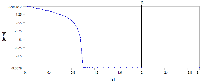
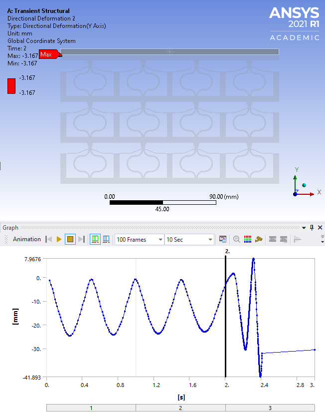 What we see here is a mistake in the model. I forgot to turn off Time Integration in Step 1 so we see the bouncing up and down for 2 seconds. It looks like the natural frequency is about 2 Hz. So at t=3 when the shaking starts, the mass is not at rest. I will rerun that with the proper setting for Step 1. I also forgot to enter some damping. In the attached model, I have entered 0.05 damping ratio at 2 Hz and turned off Time Integration in Step 1.
ANSYS 2021 R1 Archive.
August 8, 2021 at 9:57 pmAugust 9, 2021 at 1:36 ampeteroznewman
SubscriberThe second archive failed to converge during the transient step 3.
The corrective action is to put 6 linear elements across the thin beam in the 2D Plane Stress model OR switch from 2D Plane Stress to a 3D shell model.
I managed to get 6 linear elements across the 2D beam just using the Proximity Mesh control.
 That model is running now.
I showed you how to make a 3D shell. That may have less convergence problems, but it will surely solve faster.
August 9, 2021 at 3:49 amashishsv99
SubscriberHi, I will go through these archives now.
Also, why do 3D solid models have so many convergence issues? Yes, I understood how to make the shell elements and that it does not have elements on its face and so hence fewer convergence problems.
I will try the 2D model too with better and finer mesh quality and also the 3D shell element myself.
For the transient analysis, I will go through what you have sent and try to understand it first.
August 9, 2021 at 8:21 amashishsv99
Subscriber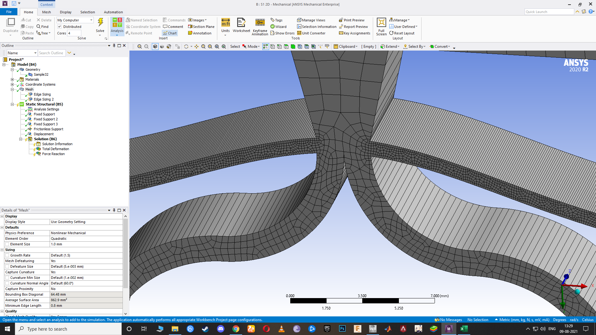 Even with such fine mesh for the 2D analysis and then having at least a 100 substeps in the analysis settings, why do I still not get the right results for F vs D? Also it gave no errors for convergence.
The link above is to the 2D structural analysis I tried. Please let me know as to why this type of model will not give the desired output. Is it because of the meshing?
August 9, 2021 at 11:34 ampeteroznewman
SubscriberI haven't yet looked at your link in the above post. I will look at that later.
I have attached a new archive that has a few changes. First, recall that in an earlier post of mine where I left on Time Integration in Step 1 and we learned that the natural frequency was 2 Hz? In the paper you provided, the authors use a variable Omega that is a ratio of the applied frequency/natural frequency. They study values of Omega of 0.5, 1.0 and 2.0. I created a 2 Hz model, which is Omega = 1.0. I created a Displacement signal that is at 2 Hz. I also put a lot more data points in that signal.
This is a challenging problem to solve. One feature that makes it challenging is that the design includes a snap-through feature. Think of the lid of a jar that has a slight dome shape. When it is unopened, the dome is down, proving that the jar has not been opened since it left the factory. After it is opened, the dome pops up. Try to use just the right amount of weight on the center of the dome to get it to sit half-way down. You can't because it is an unstable position. Just a fraction too light and it will pop up. Just a fraction too heavy and it will pop down. That is what this model has in it. I had to add some Stabilization to Step 1 of the solution to get it to the half-way point.
While I haven't let this model run for even one cycle of the transient, I hope this will have a chance of running because I left some stabilization in Step 3 and there is a slower input frequency.
August 9, 2021 at 4:11 pmashishsv99
SubscriberAlright, I will go through this model too.
Also, please look at the other file that I just uploaded in the same link, I tried the 3D shell model analysis myself by looking at yours. But the F vs D graph that I get varies from yours in terms of the value of reaction forces. Like I got 2.2N for 10mm disp whereas you've got around 5N and I'm not sure why.
File name: shell model
I will look into the transient analysis files that you have sent now.
August 9, 2021 at 4:31 pmashishsv99
SubscriberYes, the top surface in the first step should be displaced such that it creates the stagnation of reaction force to act as a vibration isolator.
August 10, 2021 at 1:00 ampeteroznewman
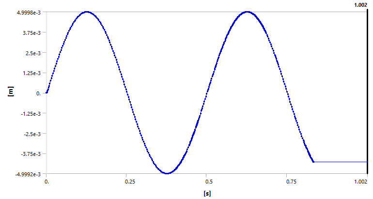
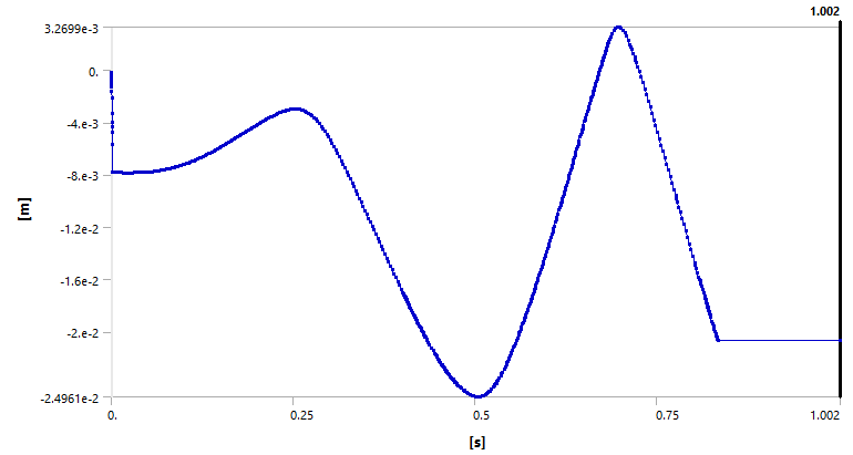
SubscriberThe last model I attached, Transient 2Hz made it 83% of the way to the end of the simulation before an element started turning inside-out. One advantage of the 3D Shell model is elements won't start turning inside-out.
Here is the input base motion:
 Here is the output motion of the top mass:
 Plotting these on the same chart looks like this:
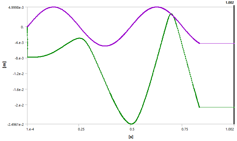 It doesn't look like the top mass is being isolated.
August 10, 2021 at 4:29 amashishsv99
SubscriberThe output seems to have more amplitude than the input ._.
Was the acceleration given in the correct direction?
August 10, 2021 at 6:07 amashishsv99
SubscriberSo does that mean it's best to use the shell model to perform this simulation to get proper results?
August 10, 2021 at 6:09 amashishsv99
SubscriberAlso please check the link I had sent, small doubts about the static analysis, I am not sure why my results vary from the one you've got for the FvsD graph.
August 10, 2021 at 1:42 pmpeteroznewman
SubscriberI opened your shell model. You extruded 5 mm while I extruded 10 mm so my force is twice as high as yours.
August 10, 2021 at 2:39 pmashishsv99
SubscriberOh okay. Also, the reaction force that we get, is it like double the actual reaction force that would occur for a unit cell? since we are only considering right half of it.
August 10, 2021 at 2:53 pmashishsv99
SubscriberI'm a little concerned about the transient analysis. Can we solve it? Or if you have any other way of solving the problem, that could be done too. I hope it can be done. I will have to show the work soon if possible or I might have to back out of this internship.
August 10, 2021 at 3:13 pmpeteroznewman
SubscriberYes, when you model half a unit cell, the force output is half. You can simply double the value to get the expected full unit cell force.
I hope there will be fewer problems running the transient analysis on the 3D shell model compared with the 2D plane stress model.
You could compare F vs D for the 2D Plane Stress and the 3D shell model to gain some confidence that they are similar.
Isn't showing the F vs D graph a way to show progress in the internship?
A big benefit of the 3D shell model is that it will solve much faster than the 2D plane stress model because there are a lot less equations in the matrix, so that will help in checking that the Transient model is correct. Another change that might help the model to converge is to switch to a linear elastic material from the hyperelastic material. You can see if this makes a difference.
Regarding the response of the 2 Hz model using 2D plane stress, the direction is correct. Looking at the model results more carefully, the displacement of the top mass due to gravity did not compress the springs to the neutral point, so when the base motion started, it was not in the null position. That is why the top mass had a large response.
In a SDOF dynamics model of a mass on a spring, it can happen that the motion of the mass can exceed the motion of the base. This is expected when the base is oscillating at the natural frequency of the system.
August 10, 2021 at 4:04 pmashishsv99
SubscriberSolving the static analysis part to get the F vs D graph was only half of the problem. This is more like a probationary time that I've been given by the professor at a research institute and asked me to solve the whole paper within this period to convert it into a full-time internship, that includes both static and dynamic analysis from the paper. So if I can finish this part by this week, that's great. If not, I might have to give up on it. Depends on what the professor would tell upon showing him my work until now. Hope we get the results at least after trying it out using the shell model and changing it to get the right output.
If you don't mind, could you please tell me more about yourself, I would like to know since you've been such a massive help to me and I would like to thank you properly, I am definitely enjoying learning things in this field and I hope to secure this internship.
August 11, 2021 at 9:57 amashishsv99
SubscriberCan you make the shell model and try the analysis one last time? If this works out somehow and if we can complete it by this weekend, it'll be great. I can show my professor the results. If not, I am actually looking for alternatives in this field, since I am very much interested in this and want to learn more, I am enjoying working in this field of mechanical and want to continue my growth in it and try what is possible.
August 11, 2021 at 10:02 amashishsv99
SubscriberI actually thought I could solve this all by myself but even this one month that I've been trying to use to learn and try out this research project, I could only reach halfway by myself but even so until now I could learn a lot and I am happy with that and I want to keep moving forward in this field. If you could give me your valuable advice and opinions, that would be really nice.
August 11, 2021 at 1:15 pmpeteroznewman
SubscriberI am happy to help, but it will take time to get to a model that reproduces this paper. There is a lot you can show the professor even today, all the issues you have learned about.
I think the fastest path to success is the 3D shell model. You need to have some basic skill in SpaceClaim to do that, such as using the Mirror button to reflect surfaces about the center of the unit cell and using the Move tool, holding the Ctrl key to make a copy to stack up 3 layers.
I was thinking about the 4 columns in the array. It seems to me that those are just springs in parallel. Since you are constraining the left and right edges with an X=0 support (frictionless), what is added by having 4 columns? The original paper had 5 columns and 4 layers. If you have no left and right edge support, then there is a difference between 1 column and 5 columns. But with a left and right edge support, there should be no difference between 1 and 4 columns, except the mass will be 4 times larger on the 4 column model than the 1 column model. However the 1 column model will solve 4 times faster!
I recommend you build a 1 column 3D shell model. You could even build a 1/2 cell model, and cut the mass in half again, but it would not look as nice as the full cell.
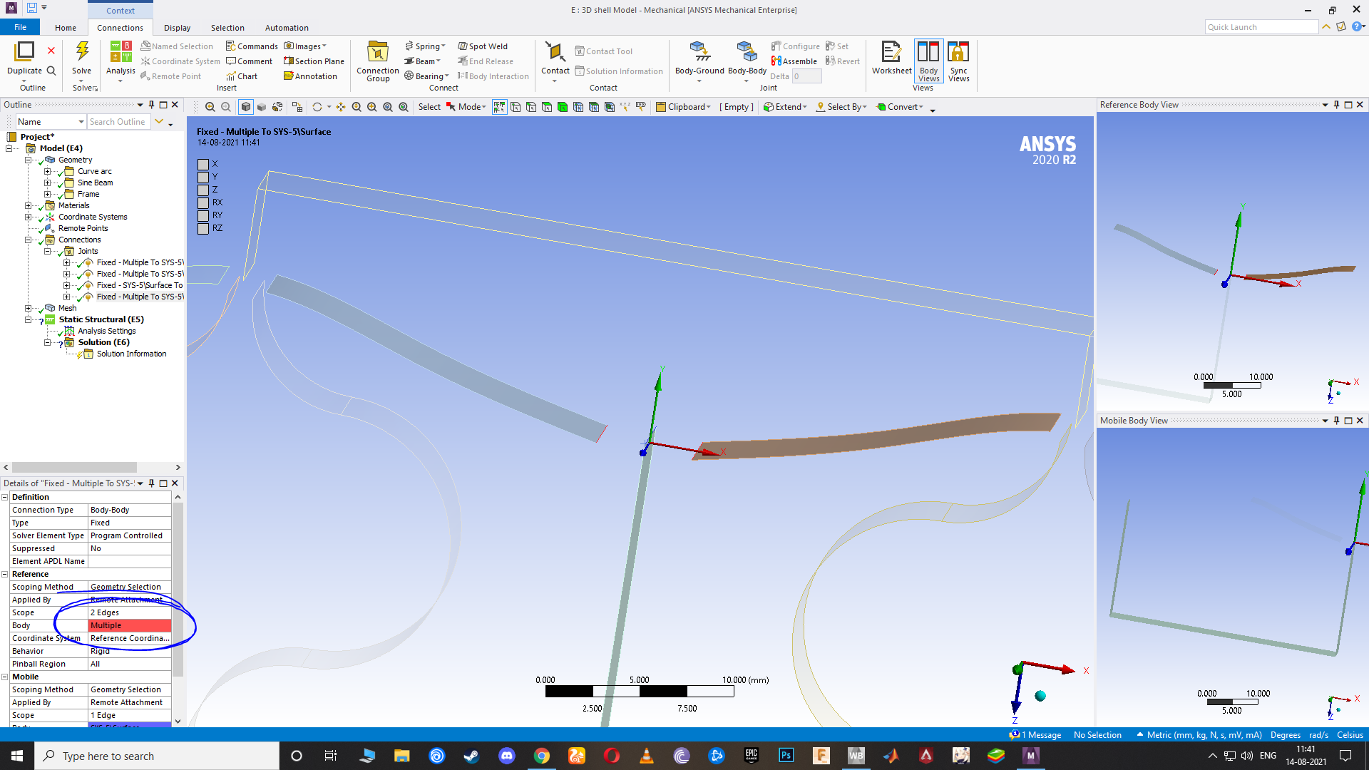
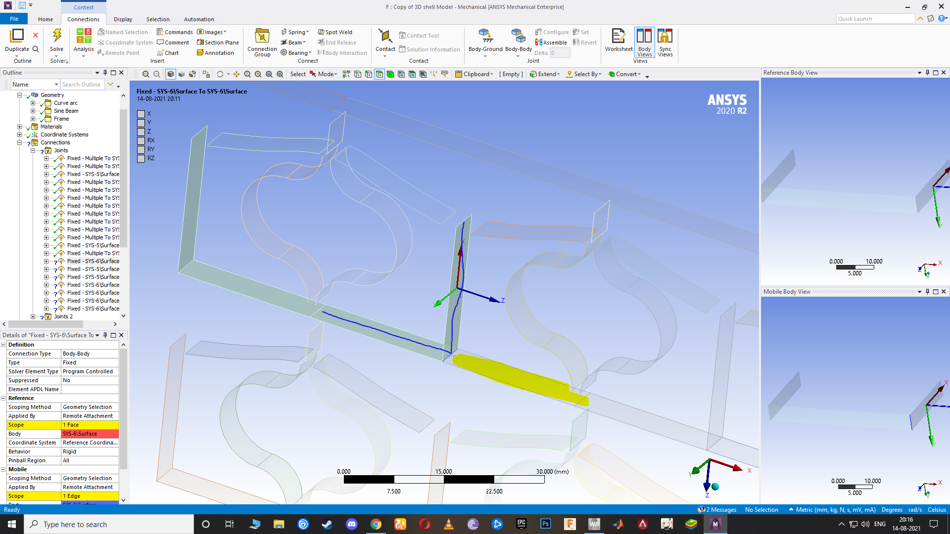
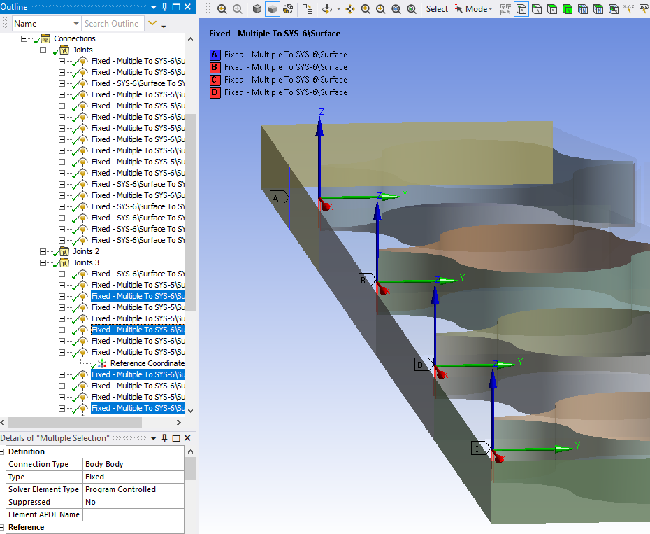
Use a Fixed Joint, Behavior = Rigid, to hold the 5 edges that come together at the top of the unit cell. The five edges are the left/right flat flexures, the left/right curved flexures and the horizontal thick frame, which is also a shell model with an edge at the center. Do the same at the bottom where 3 edges come together. Use a Fixed Joint at sides of the frame to hold the outer end of the flat flexures.
The top bar on the frame should have no extra elements. Simply add a Distributed mass on those elements to apply the needed mass.
August 11, 2021 at 3:00 pmAugust 11, 2021 at 4:34 pmpeteroznewman
SubscriberSomething like this:
 I used a Beam element to go between the layers. It may be possible to change the cross-section from rectangular to a tapered beam. Not sure about that. It could have been a sheet, but then the thickness would be constant, but it is a little easier to do if you haven't created beams before.
 Fixed Joints (Behavior = Rigid) is used to tie together the pieces at each intersection and jump the gaps.
August 12, 2021 at 12:48 amashishsv99
SubscriberWow OKAY, got it. Hope this helps us in getting to the actual results a little faster.
August 12, 2021 at 3:50 ampeteroznewman
SubscriberI found there is some value in having multiple columns, it stabilized the cells from rotating about Y axis.
The example above is a 5 mm extruded depth, but I think 10 mm is better because the shape deflects out of plane, but again, maybe multiple columns is better.
August 12, 2021 at 5:24 amashishsv99
SubscriberOkay alright. I guess multiple columns is a better option, just the way they have tried it out too.
Actually, you can send me the files of these once you have inserted multiple columns. I will also simulate it, could be a little faster.
August 12, 2021 at 10:38 amashishsv99
SubscriberHi, I actually had a conversation with my professor and told him I will show him whatever the progress I have made until now on Monday, and then he can talk about the internship and my chances at converting it. So if he asks me when I can complete the dynamic analysis and if I can do it at all and show him the exact results, what should I reply to him with? Can we actually get the dynamic response of it, or is it going to be difficult? Like I am not sure how long he would hold on to me for this and even I want to have that assurance that I can show him the end results and work on it or I would say it's best for me to look for different opportunities if it is going to take weeks. I have been on a probationary period for a month, so I am not sure how much longer the professor would wait for my full report.
August 12, 2021 at 2:16 pmpeteroznewman
SubscriberI was able to connect the single column and add enough extra constraints, such as Fixed Rotation, and Displacement of X and Z = 0 on a few nodes to limit the spring to motion along the Y axis without having to make more columns. To simplify as much as possible, I used a linear material, Stainless Steel, which is a lot stiffer than the TPU, but I put a lot more mass on the top to get the deformation to the flat part of the Force Deflection curve. It is not quite flat because there is a mistake I found later that I haven't fixed yet.
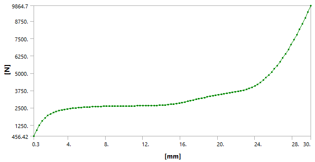 The good news is that when I turned on Gravity, the solver pulled the top down to the same deflection. I ran a Modal analysis, and found the first mode was at 12 Hz. I made a three step transient, step 1 gravity in 0.1 s, step 2, no change till 0.2 s, step 3 a 12 Hz 4 mm sinusoidal base motion will 1.2 s. I got a result similar to what the paper shows, excellent isolation. Because there were so few nodes, the Transient solution finished in 9 minutes! Before I was waiting hours.
 I checked the Connection Elements created by the fixed joints and see I made one mistake and have one extra edge that I will remove and rerun the analysis to get final results.
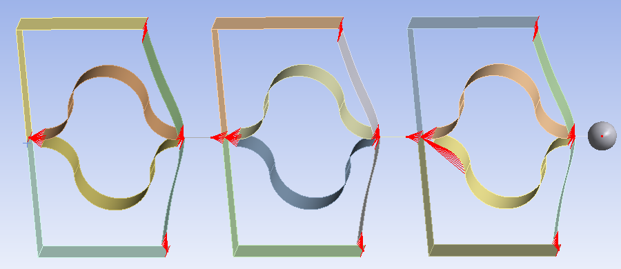 I think you can get to this point (without the mistake) by Monday.
August 12, 2021 at 2:58 pmashishsv99
SubscriberWowwwwwwwww, that is actually working out pretty well, I think this can be done. I have to look into the model and the node constraints you were talking about since I am not sure what they are. I will look into the whole thing once you send the files. I think I understood most of the part, will get clarity once I look at it in the mechanical. Thank you so much, this is looking great. I am having hopes now.
Once I fully understand this I think I can switch back to TPU material and run it too, changing the mass.
August 12, 2021 at 6:14 pmpeteroznewman
SubscriberWith the mistake fixed, the F vs D curve flattened out.
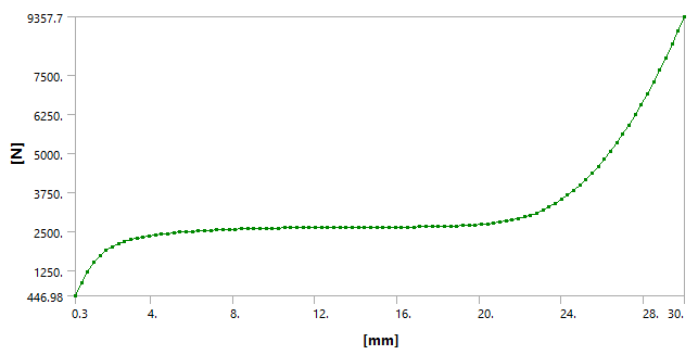 The response also looks cleaner and I forgot to include any damping in the model, so the result is impressive.
 To be effective in your internship, you need to develop geometry creation and editing skills, model building skills, and simulation debugging skills. I gave you the 3D surface model of the two springs of a half cell in the attachment (Geometry Options for Spring) in my August 7 reply on P2 of this discussion. I have attached just the geometry here for you in a 7z file below.
Use the Mirror button to reflect surfaces about the center of the unit cell then use the Move tool, holding the Ctrl key to make a copy to stack up 3 layers. Instead of the Move tool you can also use the Linear Pattern tool to copy them down. You will have to sketch out some lines for the Frame and extrude those out into surfaces. I'll check in later to see how it's going.
August 13, 2021 at 2:34 pmashishsv99
SubscriberOkay, will try out the modeling part.
Also, a doubt, the output of disp vs time, its curve is not similar to the ones in the research paper, right? Is it because of the material being used?
August 13, 2021 at 2:43 pmAugust 13, 2021 at 2:44 pmashishsv99
SubscriberIf you could send me the dynamic analysis file, I could go through it too and understand what procedures are followed in it.
I will then have a look at it and try it out by myself
August 13, 2021 at 4:01 pmpeteroznewman
SubscriberGood progress, I see three springs. Do you have the frame? Draw a line from the center of the horizontal piece of frame and another line along the center of the vertical piece. The lines should meet in the corner. Extrude out one half the frame and them mirror that over. Create a center line for the short piece at the top of the springs that reaches up to the beam and extrude that out. Then copy those frame pices down for the 3 layers. When you show this next step, hide the template 2D surface and all the planes so it is easier to see the surfaces you will mesh.
Next step is to connect those surfaces in Mechanical with Fixed Joints.
I used a 4 mm amplitude at 12 Hz in my model. I can create a 5 mm sine wave for you if you want that. The frequency depends on the material you choose. You need to use a linear elastic material if you want a Modal analysis to compute the first natural frequency. If you use TPU, you can just turn on gravity and see the natural frequency of the bouncing in a Transient Structural, with a Fixed Support on the base.
August 14, 2021 at 1:06 amAugust 14, 2021 at 1:09 amashishsv99
SubscriberAbout the transient analysis, I will try it out myself for the TPU material and give it a 5mm sine wave. I will see how you have done it with the structural steel material and understand that and then rest I can try it out myself and see how it works. I will then share the results here too for your suggestions.
August 14, 2021 at 1:11 amashishsv99
SubscriberI can also try it out for the whole (3x4) metastructure right?
Please share the transient file once done, I can go through it and understand that and I will try out the rest by myself and show it to you.
August 14, 2021 at 2:21 ampeteroznewman
SubscriberGreat job with the geometry! One more edit to the horizontal frame bodies, draw a line across them at the center to create an edge to use in the Fixed Joints. If you want to do a 3x4 along the X axis, you copy everything except the three vertical frame bodies on the -X side, otherwise you will get double bodies in the center. You will also have to draw lines and extrude into sheets for the top part of the frame, which I left out of the single column version. Doing 3x4 will increase the number of Fixed Joints you have to make in the next step.
Use a Static Structural model to import that geometry. Assign the correct material (TPU) and thickness values to each sheet. Make all the Fixed Joints to tie the groups of edges together. It doesn't matter which edges are on the Mobile side and which edges are on the Reference side. The Fixed joints will have a Behavior of Rigid.
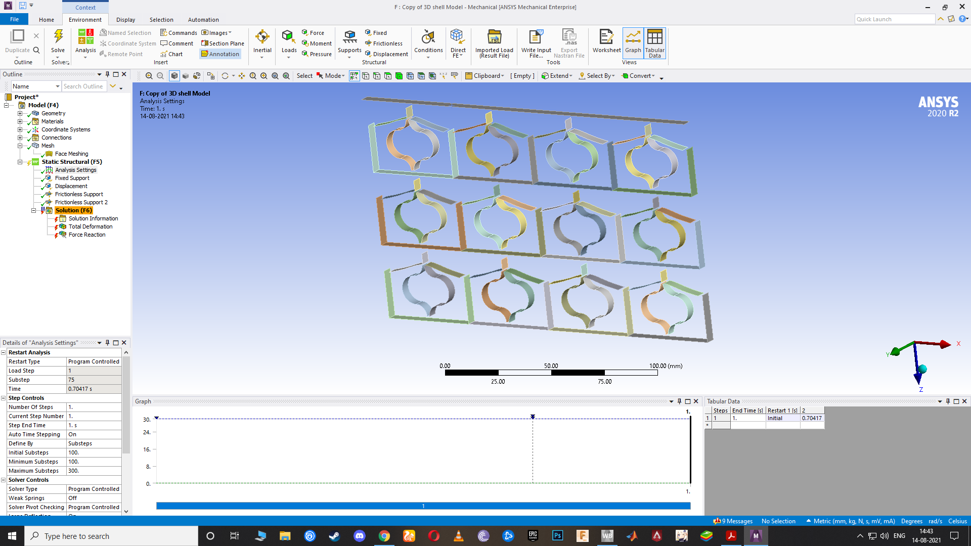
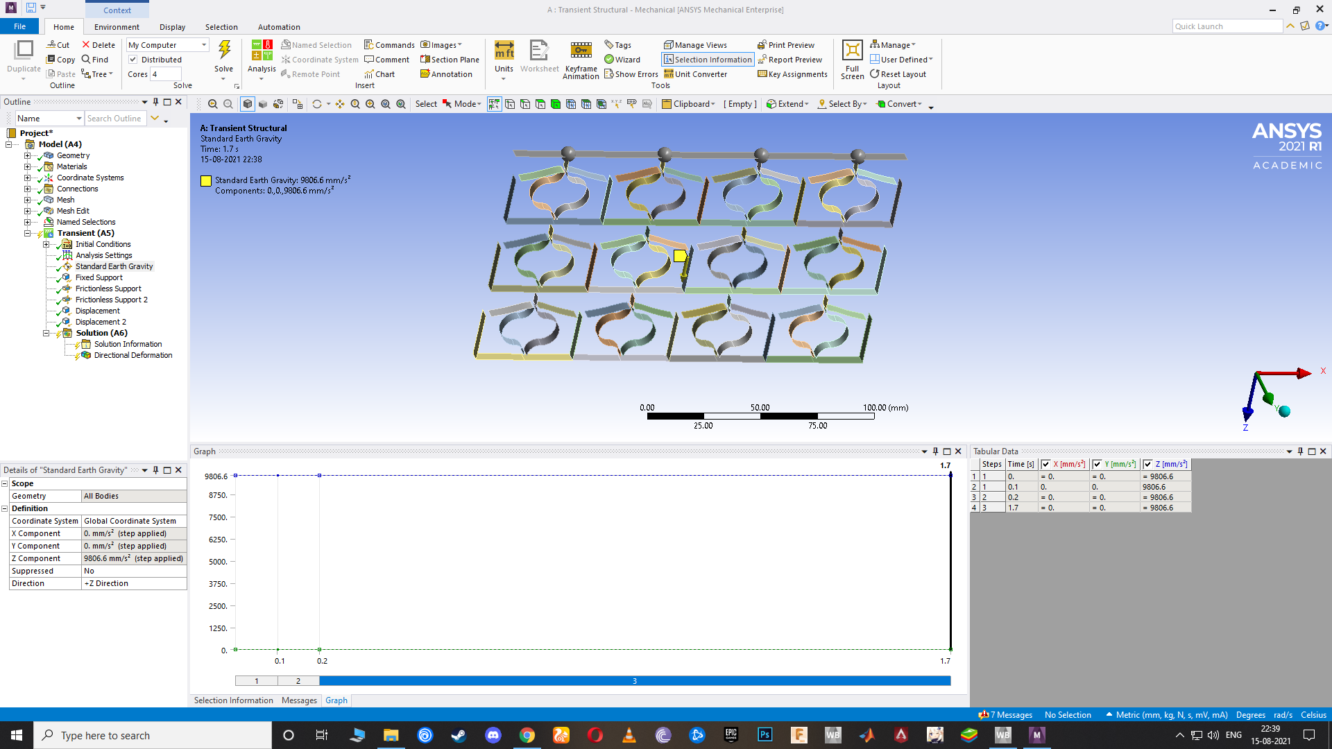
Create a Fixed Boundary condition on the bottom and a Displacement Boundary Condition on the top to push down the top by 30 mm and obtain the F vs D curve. You could have Standard Earth Gravity turned on too. After it has solved, determine the mass that must be added to the top to create the deflection needed to reach the flat part of the F vs D curve. Add that as a point mass to a single column or a distributed mass for a 3x4 array to the bodies along the top.
Drag and drop a Static Structural onto the Model cell, and in this, use just the Fixed Support on the bottom and Standard Earth Gravity to check that the model converges at the correct displacement.
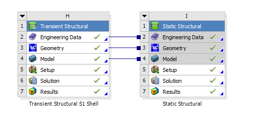
Drag out a Transient Structural and drop that on the Model cell of the Static Structural. Use just the Fixed Support on the bottom and Standard Earth Gravity in step 1 and let the mass bounce up and down to get the frequency of vibration. Let me know what that is if you want me to create the 5 mm sine wave.
Finally, drag out a Transient Structural and drop that on the model cell of the Static Structural and do the three step analysis.
I will be available to help you all day Saturday and all day Sunday. Think about your professor reading this discussion. I expect he would have high confidence that you have the skills he needs when he sees you built the whole model and worked through the debugging phase without starting with the answer in hand.
August 14, 2021 at 3:35 amashishsv99
SubscriberOkay, I will do this today and show it to you. I will have to finish this in the next two days and show it to my professor. I will work completely on this until I finish it within the next two days. Please guide me.
August 14, 2021 at 5:22 amashishsv99
Subscriber"One more edit to the horizontal frame bodies, draw a line across them at the center to create an edge to use in the Fixed Joints" I did not understand this statement exactly.
August 14, 2021 at 5:34 amAugust 14, 2021 at 5:37 amashishsv99
SubscriberWhat I did was create the first row and then copy-paste move that twice for the next two rows. The first row I designed only using offset and line tools.
August 14, 2021 at 5:58 amAugust 14, 2021 at 6:13 amAugust 14, 2021 at 6:34 amAugust 14, 2021 at 7:57 amAugust 14, 2021 at 8:01 amashishsv99
SubscriberWhat other mistakes could I have made while performing this static analysis according to you? I feel there is something else too
August 14, 2021 at 9:15 amAugust 14, 2021 at 10:09 amashishsv99
SubscriberPlease have a look at the link, I tried a lot of changes but it is giving convergence issues I guess. What all do I have to change in it? Please look at the file in the link though, since it will give a clear idea as to what I have done. Tried it all myself, so I am sure there will be mistakes in it.
August 14, 2021 at 11:08 ampeteroznewman
SubscriberWow, a lot of progress!
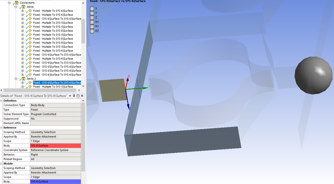
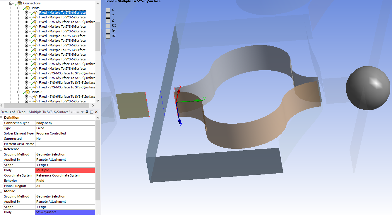
Below is the split in the face that is needed to make the Fixed Joint. Go to SpaceClaim. Use the Split button and Ctrl-click all the horizontal faces in one column then click the Cut button and select of of the vertical faces at the center to split the faces. Repeat for the other 3 columns. Then go and repair each fixed joint and change it from using a face to using only edges. The reason for this edit is that the Fixed Joint with behavior Rigid makes the whole horizontal frame rigid instead of flexible.
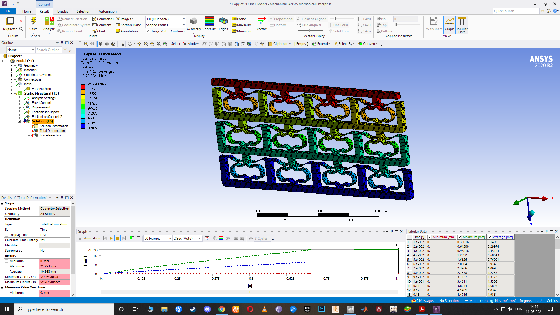
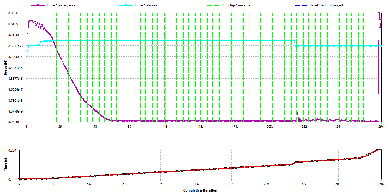
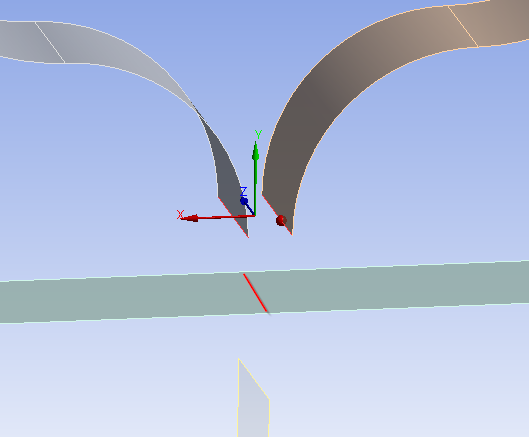 Below is the Rigid Elements that cover your structure, you can see it covers way too much compared with the example I provided in one of my previous comments. This is why your F vs D is not correct. Look carefully at which edges are included in each joint. This plot can only be seen after the solver has run on the model. Click on the Solution Information folder where you see the Force Convergence Plot, except the main graphics window automatically switches to Worksheet. Click the Geometry tab at the bottom left of the main window to see this plot.
 I will send this now and keep looking at the rest of the model. What time zone are you in? I am in the Eastern US Time Zone. I posted this at 7:08 AM. What time does it show for you?
August 14, 2021 at 12:29 pmashishsv99
SubscriberIt shows 4:08PM for me
August 14, 2021 at 12:31 pmashishsv99
SubscriberI have got a small work, I will be back in 2 hours from this post, that'll be 8pm or so for me after which I will sit with you and work on this until late night.
August 14, 2021 at 12:34 pmAugust 14, 2021 at 1:50 pmpeteroznewman
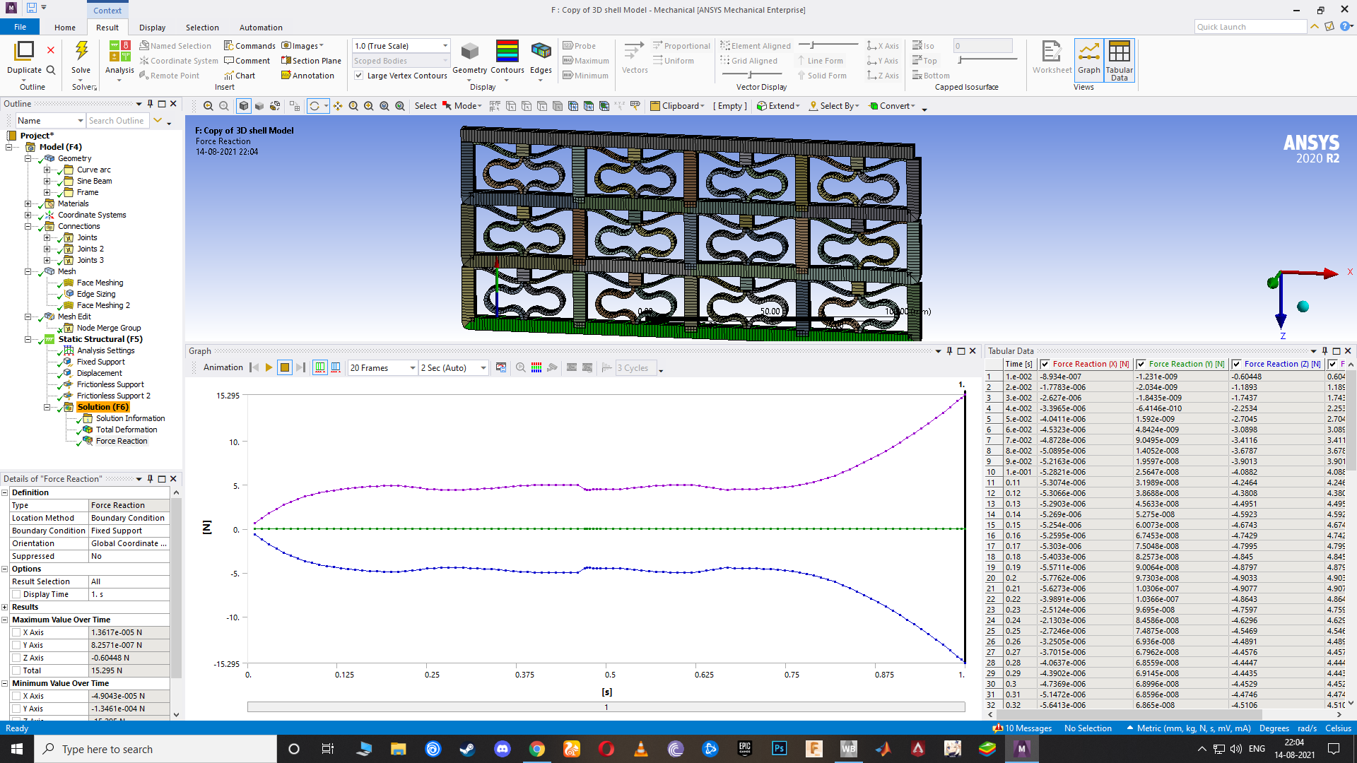
SubscriberBelow is the F vs D graph for TPU without Earth Gravity, there is a glitch at 0.5 seconds.
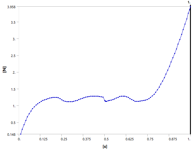 Below is the F vs D graph for TPU with Earth Gravity, which seems to smooth out the glitch.
 Below is the F vs D graph for Stainless Steel, a linear material, without Earth gravity. The linear material is more stable over the flat part of the curve.
 August 14, 2021 at 2:25 pm
ashishsv99
SubscriberWhy is the flatness not stable for TPU material though?
August 14, 2021 at 2:28 pmashishsv99
SubscriberI want to at least finish the static analysis by tonight and get the correct response curve using TPU material using this method. Can finish the transient analysis by tomorrow. Hope this is possible.
August 14, 2021 at 2:44 pmpeteroznewman
SubscriberThe nonlinear properties and the low stiffness contribute to the lack of flatness.
Below is a Transient Structural run with a 0.126 kg point mass added based on the 1.24 N force at the top of one of those smooth waves of TPU with gravity as the only input. Z = Free at the top.
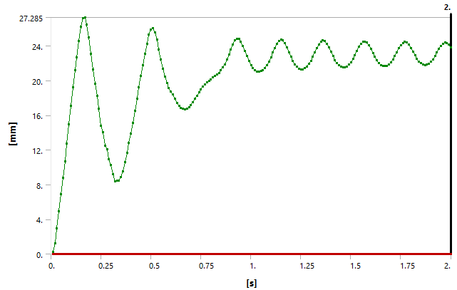 If you perform an FFT on the data from 1 to 2 seconds, the frequency is 4.688 Hz. That is the natural frequency of this system.
August 14, 2021 at 2:44 pmAugust 14, 2021 at 2:47 pmAugust 14, 2021 at 3:33 pmashishsv99
SubscriberOkay I fixed it by combining body in SpaceClaim and repaired the joints, will run it and see
August 14, 2021 at 4:10 pmAugust 14, 2021 at 4:16 pmpeteroznewman
SubscriberIn Mechanical, you can do a Node Merge as long as the nodes line up along the edge (same number).
August 14, 2021 at 4:35 pmAugust 14, 2021 at 4:35 pmashishsv99
SubscriberBut can we not smooth out the flatness even further? 2D analysis gave a really smooth curve
August 14, 2021 at 4:47 pmashishsv99
SubscriberIt is like each row is going through the quasi-zero process one at a time, can see it when I play the deformation.
I have updated the model in this link. You could check it out and let me know if any changes are necessary. I will sleep now. Please let me know what all I have to do for tomorrow. I have to finish this by tomorrow night. I will look into the transient analysis and what all you had sent me until now and try it out.
August 14, 2021 at 9:28 pmpeteroznewman
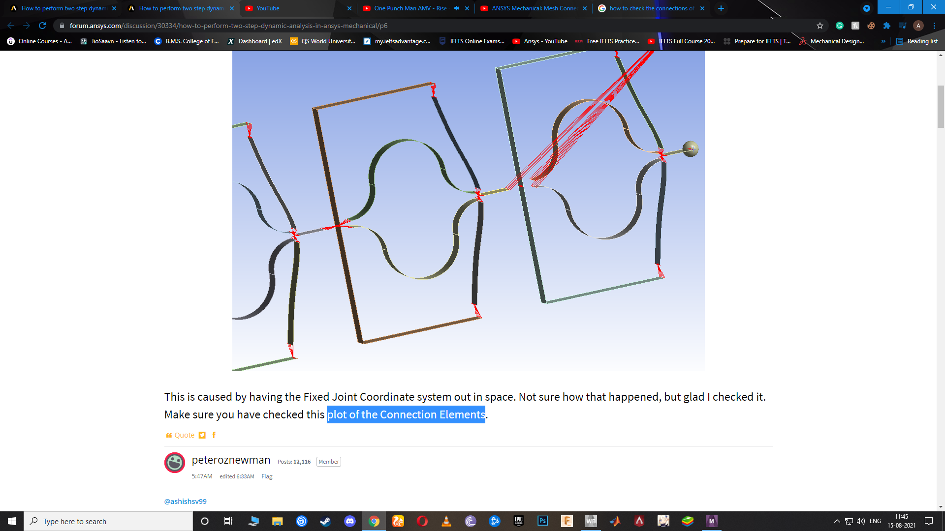
SubscriberThis is my model. I found a mistake in the Connection Elements in one of the Fixed Joints. This kind of mistake can hurt the convergence.
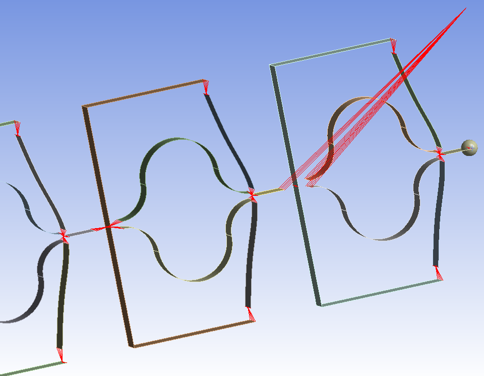 This is caused by having the Fixed Joint Coordinate system out in space. Not sure how that happened, but glad I checked it. Make sure you have checked this plot of the Connection Elements.
August 15, 2021 at 12:47 ampeteroznewman
SubscriberHere is a completed transient with TPU and a 5 mm amplitude input motion. It would be interesting to simulate another few seconds. This took 53 minutes to simulate.
 I fit a straight line to the Uniaxial TPU data and came up with a modulus of 41.4 MPa. I'm going to convert this model to a Linear Material and see what it looks like.
August 15, 2021 at 1:32 ampeteroznewman
SubscriberI am looking at your model now. I see the version of ANSYS you used in the last iteration was 2020 R2, but I understand you have access to both versions, since I have been working in 2021 R1.
It may turn out to have a smoother motion if Earth Gravity was on in Step 1 then the motion began in Step 2.
Looking through the Solution Output, these warnings were issued:
*WARNING*: 24 MPC equations were released for the rigid constraint surface identified by real constant set 249 due to overconstraint detection logic.
*WARNING*: 24 MPC equations were released for the rigid constraintsurface identified by real constant set 265 due to overconstraintdetection logic.
*WARNING*: 6 MPC equations were released for the rigid constraintsurface identified by real constant set 269 due to overconstraintdetection logic.
I got those warnings too, and they mean that the solver has to ignore some of the things you asked it to do because it can't do two things at once: (1) Use a node in a joint and (2) use a node in a boundary condition. I eliminated those warnings by creating boundary conditions using nodes near the point when the joint was, while not using any nodes that were in the joint (on the edges). Not sure if it will make a difference in the output though.
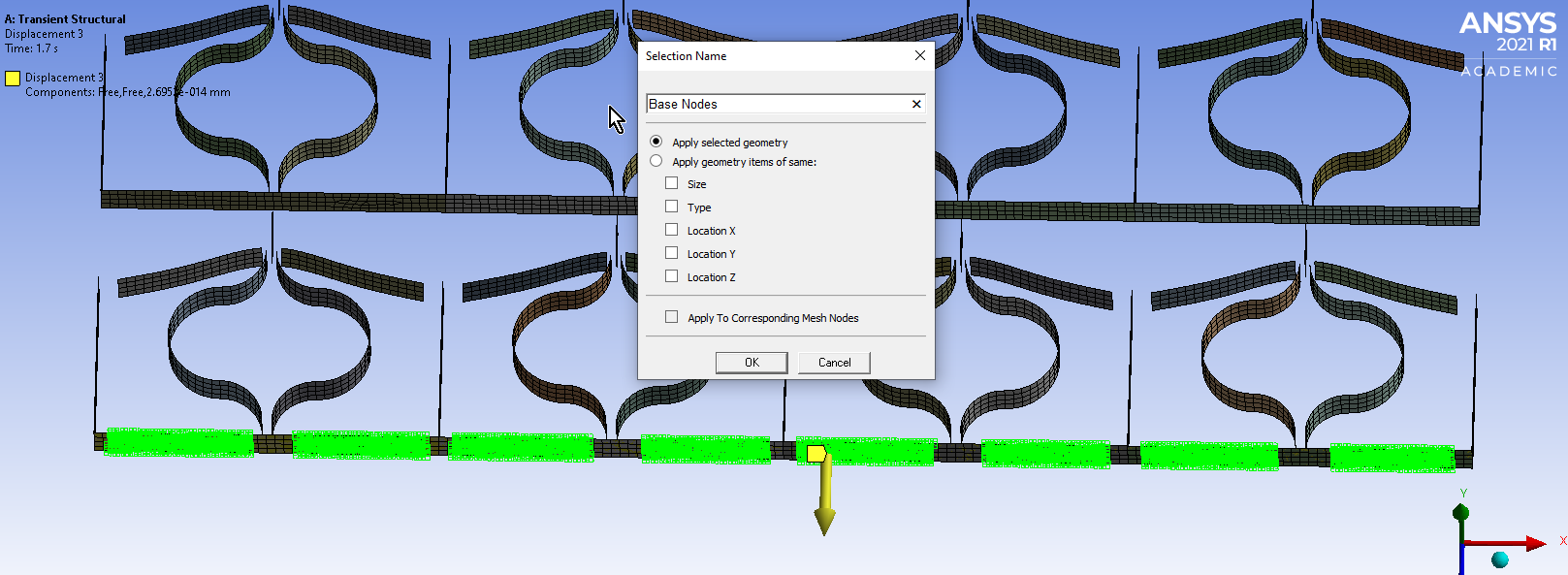
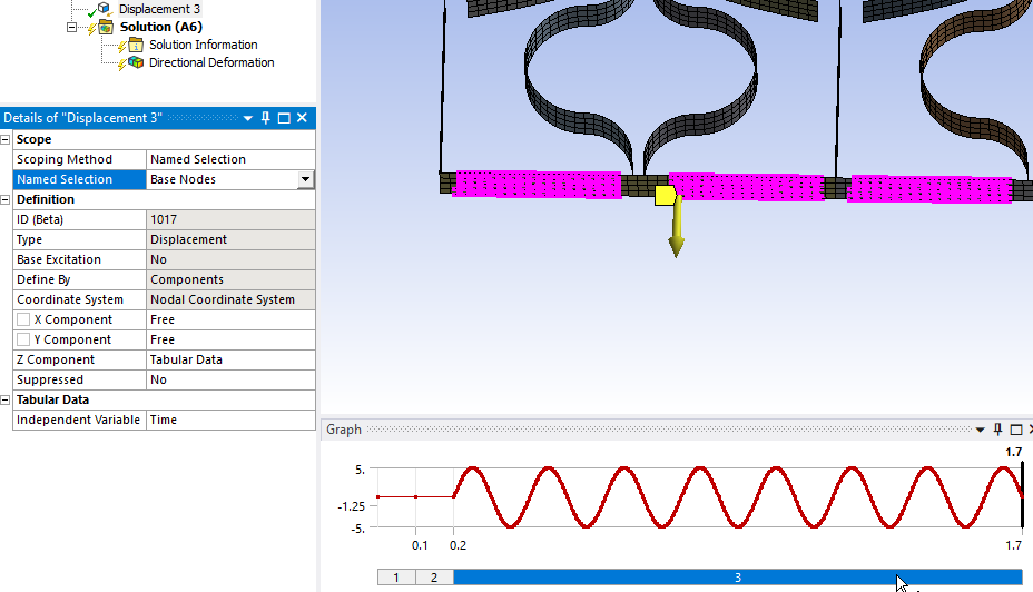
For example, since there is an edge in the center that is part of a Fixed Joint, I picked 8 nodes on the base to use in the Displacement 3.
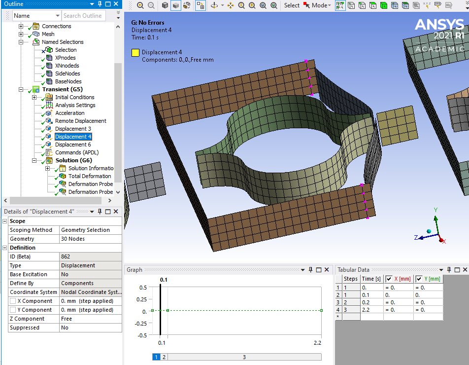
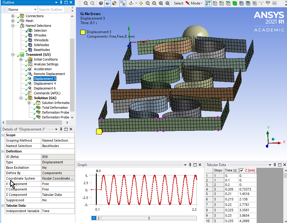 In order to apply an X = 0 constraint to the vertical sides of the frame (frictionless support) without touching the nodes along the top edge that were involved in a Fixed Joint to the spring, I picked a row of nodes just below that and also a row along the bottom corner. I held both X and Y = 0 to keep the cells in the XZ plane.
 August 15, 2021 at 1:50 am
ashishsv99
SubscriberHow do we check the connection of the elements?
August 15, 2021 at 1:52 amashishsv99
SubscriberYes I have both 2020R2 and the 2021R1 which is student edition.
August 15, 2021 at 1:54 ampeteroznewman
SubscriberGood morning.
August 15, 2021 at 1:55 amashishsv99
SubscriberOkay, I will try the transient analysis today and will share whatever I can make out of it.
August 15, 2021 at 1:56 amashishsv99
SubscriberThe output that you got while using TPU isn't dampening at all?
August 15, 2021 at 1:58 amashishsv99
SubscriberOkay let me know if it makes it better using the elastic model, I will try the same.
August 15, 2021 at 1:58 ampeteroznewman
SubscriberThe TPU output had 5% damping at 5 Hz
Here is the same model, but with a Linear Material E = 41 MPa instead of a Hyperelastic Material.
 Increased E to 90 MPa and now the flat part of the curve is about 1.22 N which is where the TPU was.
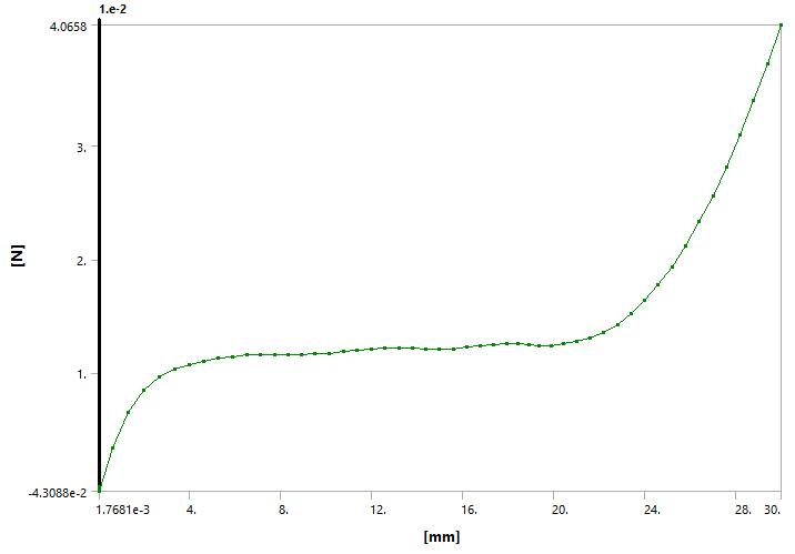 This requires about the same 0.125 kg mass, but when the Modal solution is run, the natural frequency is 11.6 Hz.
August 15, 2021 at 2:11 ampeteroznewman
SubscriberYou will have less trouble using a Linear Material getting this to converge.
August 15, 2021 at 4:02 ampeteroznewman
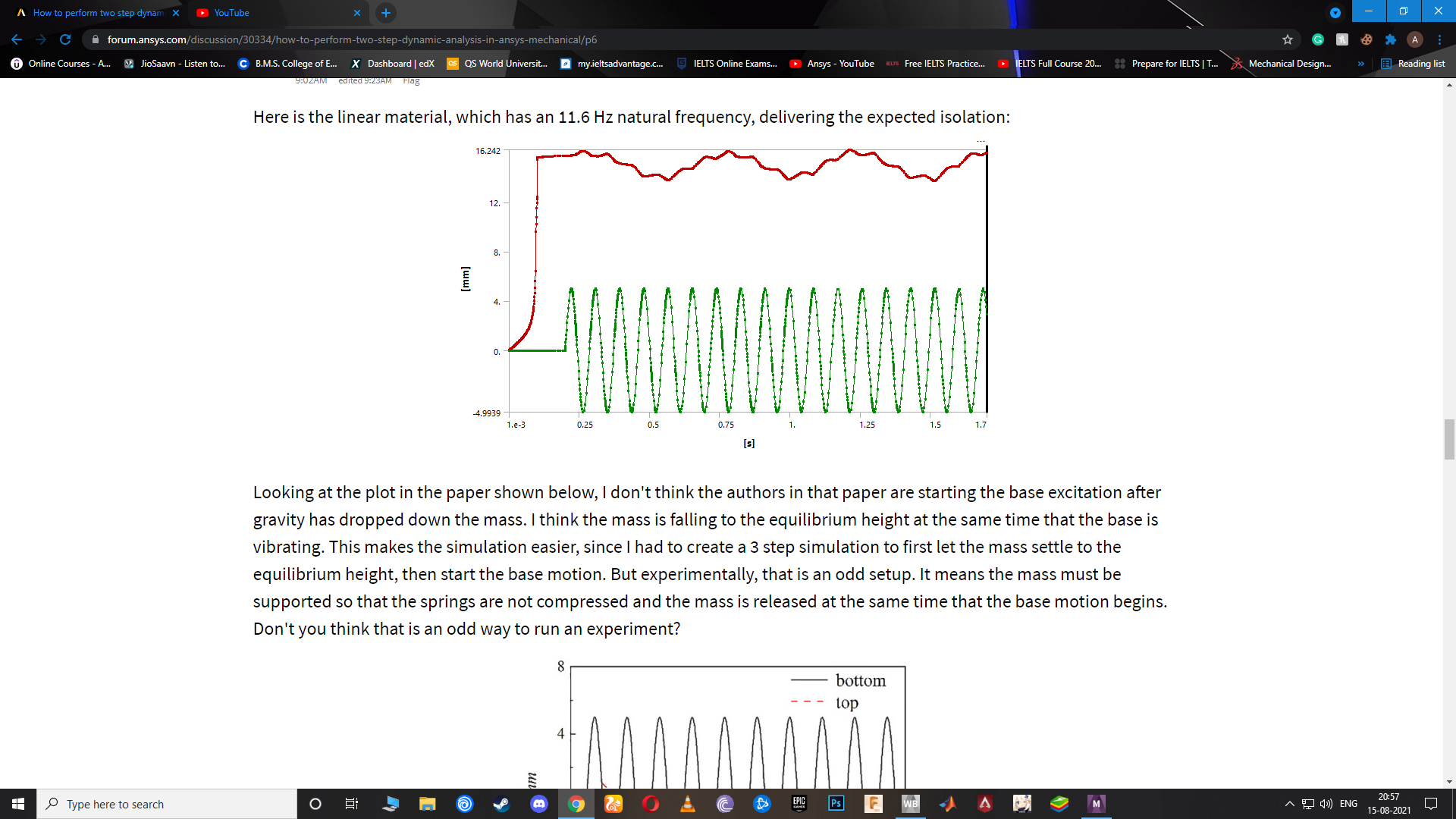
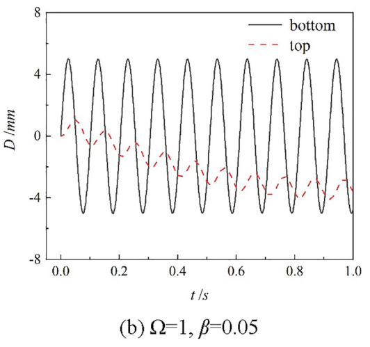
SubscriberHere is the linear material, which has an 11.6 Hz natural frequency, delivering the expected isolation:
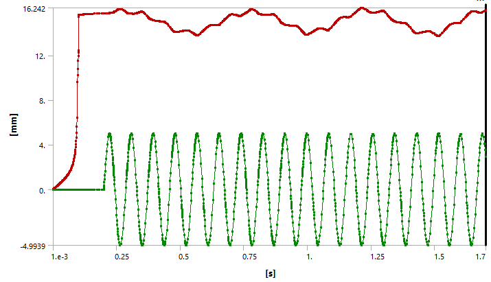 Looking at the plot in the paper shown below, I don't think the authors in that paper are starting the base excitation after gravity has dropped down the mass. I think the mass is falling to the equilibrium height at the same time that the base is vibrating. This makes the simulation easier, since I had to create a 3 step simulation to first let the mass settle to the equilibrium height, then start the base motion. But experimentally, that is an odd setup. It means the mass must be supported so that the springs are not compressed and the mass is released at the same time that the base motion begins. Don't you think that is an odd way to run an experiment?
 August 15, 2021 at 6:17 am
ashishsv99
SubscriberYes, it doesn't seem like the right procedure to follow, you would rather want to let the weight bring the structure to a quasi-zero position and then excitation to be applied.
August 15, 2021 at 6:18 amAugust 15, 2021 at 9:12 amashishsv99
SubscriberOkay, so I was trying to do this static analysis with having point mass over each column and then turning on gravity.
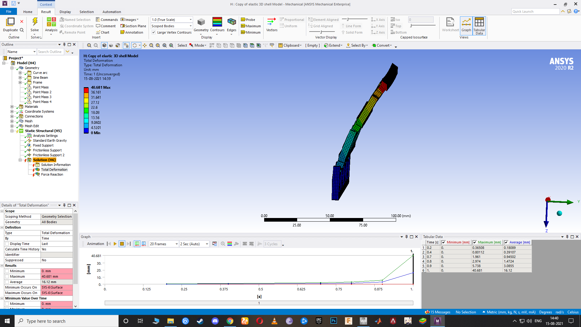 But it turned out to be this way. How do I make it translate only in Z?
I tried your method to restrict the nodes from displacing in X and Y but I cannot apply that boundary condition. If I select the node and press apply in the geometry, it doesn't work.
August 15, 2021 at 9:20 amAugust 15, 2021 at 9:24 amashishsv99
SubscriberI am not sure with the boundary conditions and analysis settings that I have to be using for the transient analysis. Please let me know about it and I will finish this work by today. Can do it.
August 15, 2021 at 10:19 ampeteroznewman
SubscriberThis plot can only be seen after the solver has run on the model. Click on the Solution Information folder where you see the Force Convergence Plot, except the main graphics window automatically switches to Worksheet. Click the Geometry tab at the bottom left of the main window to see this plot.
Returning to the question of starting the simulation with the spring uncompressed and the mass out of equilibrium with gravity as implied by this graph.
 In the current simulation, I changed the sign of the motion to agree with the sign convention above. As you can see below, the mass starts falling, but the spring seems much too weak and the mass falls a large distance. Perhaps instead of a stronger spring, a larger base motion would help?
 August 15, 2021 at 10:22 am
peteroznewman
SubscriberYou have to use a Named Selection of Nodes, then use the Named selection to put them in the Boundary Condition.
When you include Y=0 on the nodes on the top and bottom of the vertical frame walls, that will stop the stack from tipping over. The stack is not stable on its own. It might be more stable if the extrusion depth was increased from 5 mm to 10 or 20 mm.
August 15, 2021 at 1:32 pmAugust 15, 2021 at 2:30 pmashishsv99
SubscriberSorry I was a little late, I will start working on this now as soon as I finish my dinner and then sit on it until I finish it off even if it gets late.
August 15, 2021 at 3:22 pmAugust 15, 2021 at 3:27 pmashishsv99
Subscriber In the plot shown in the paper, I feel like they have done what you had done first, that is compressed and give base excitation. The output of it then is adjusted to make it look like it started off from 0 displacement. So I feel like that shouldn't really matter as long as we can get the same kinda damping effect in our simulation.
August 15, 2021 at 3:31 pmAugust 15, 2021 at 3:42 pmAugust 15, 2021 at 3:49 pmpeteroznewman
SubscriberWhen you click in the pull down, there are no named selections?
 The wiggles in the model are a combination of a low frequency oscillation overlaid with the driving frequency of the base. I'm not sure why we don't get the same wiggles as in the paper. I did a few one-step simulations but the top mass had much larger amplitudes than the base.
August 15, 2021 at 4:15 pmashishsv99
SubscriberNo I am not getting any pull down options in it
wait I will rather share the file
August 15, 2021 at 4:21 pmashishsv99
SubscriberPlease check my model and let me know every changed and additions that I've to make
August 15, 2021 at 4:22 pmashishsv99
SubscriberLet us see how the response would be with this 3x4 model though, now that we followed the same procedure as them. Would like to see it compared to theirs.
August 15, 2021 at 4:58 pmpeteroznewman
SubscriberIt seems there is a bug in 2020 R2 and you can't select Nodal Named Selections for Displacements.
Open the project in 2021 R1 and you can.
August 15, 2021 at 5:03 pmashishsv99
SubscriberOkay
August 15, 2021 at 5:10 pmAugust 15, 2021 at 5:12 pmashishsv99
SubscriberI have to add the base excitation, that's it I guess
August 15, 2021 at 5:19 pmAugust 15, 2021 at 5:21 pmashishsv99
SubscriberBy the way how did you give the inputs for the sine wave excitation? Like the tabular data? Can use a graph plotter online and get the tabular values for it
August 15, 2021 at 5:29 pmAugust 15, 2021 at 5:42 pmashishsv99
SubscriberOkay I will repair that
August 15, 2021 at 5:49 pmpeteroznewman
SubscriberYes, you can use an online tool to generate a sine wave tabular data. Just make sure you get 500 points per second.
You have matlab, so you should download the free Vibrationdata Signal Analysis Package from Wordpress from the link below.
It is a zip file. Unzip to a folder. In matlab, add that folder to your Path. Type vibrationdata at the command line.
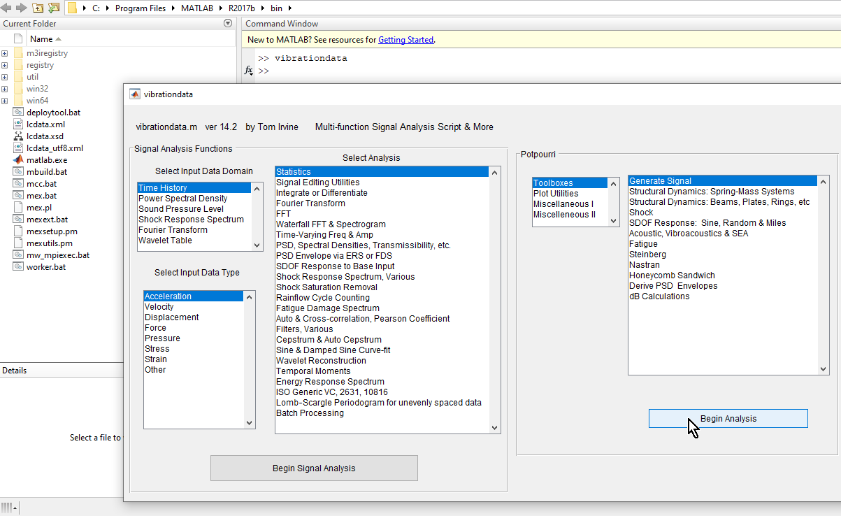 Click Begin Analysis. Fill out the entries, then click Calculate. Then type in a file name and click Save.
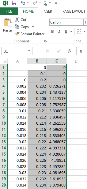
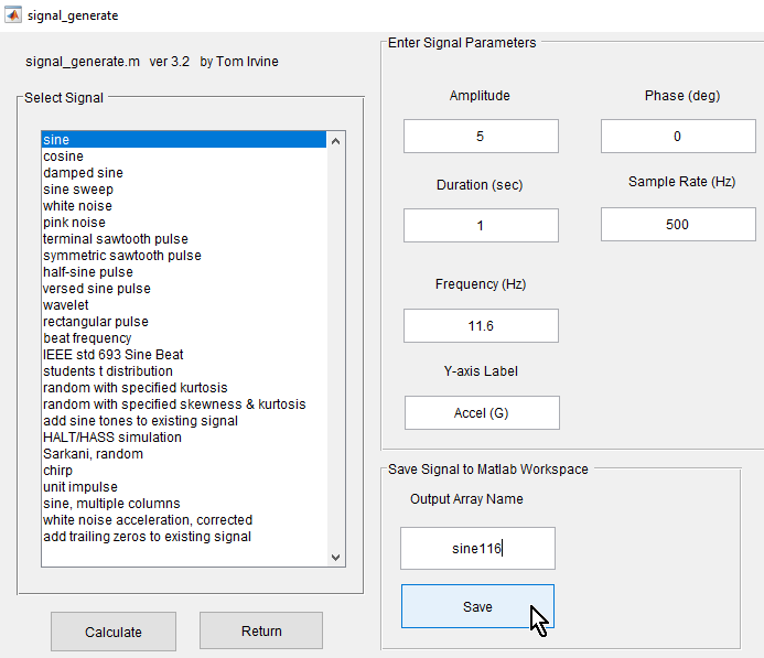 That variable sine116 is now in the matlab environment. It has Time and Displacement columns. Highlight the rows and copy, the paste into Excel for adding 0.2 to the Time column, then add a row for time = 0, 0.1 and 0.2 with Displacement = 0.
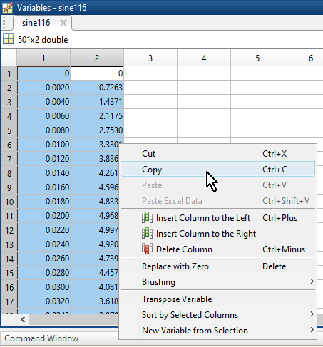 After you make a new time column, copy those 2 columns and 503 rows so you can paste them into Mechanical.
August 15, 2021 at 5:52 pmpeteroznewman
SubscriberAugust 15, 2021 at 6:07 pmAugust 15, 2021 at 6:09 pmAugust 15, 2021 at 6:12 pmpeteroznewman
SubscriberAugust 15, 2021 at 6:12 pmashishsv99
SubscriberMade all the changes said by you and updated them, please check the file from the link.
August 15, 2021 at 6:14 pmpeteroznewman
SubscriberHow to fix the error.
Suppress both Frictionless Supports, You have Nodal Displacements to replace them.
The Displacement 3 on the bottom faces includes nodes used in the Fixed Joint to the bottom rail.
Create a Nodal Selection of nodes on the bottom rail that avoids the nodes used in the Fixed Joint.
 August 15, 2021 at 6:20 pm
ashishsv99
SubscriberThe nodal selection called top, I should add it to the transient as well as modal right?
August 15, 2021 at 6:22 pmpeteroznewman
SubscriberYes.
August 15, 2021 at 6:27 pmAugust 15, 2021 at 6:29 pmashishsv99
SubscriberYes I do have a skype account, I guess it will be faster to share my screen and work on it
August 15, 2021 at 6:30 pmashishsv99
SubscriberFrictionless supports suppressed
August 15, 2021 at 6:31 pmpeteroznewman
SubscriberAugust 15, 2021 at 6:32 pmashishsv99
SubscriberI did not understand the base nodes part. Why not use the faces instead?
August 15, 2021 at 6:35 pmAugust 15, 2021 at 6:35 pmashishsv99
SubscriberUpdated the comment
August 15, 2021 at 6:37 pmpeteroznewman
SubscriberGot it.
August 15, 2021 at 6:38 pmashishsv99
SubscriberOkay, so nodes being used elsewhere cannot be used for boundary conditions.
August 15, 2021 at 6:44 pmpeteroznewman
SubscriberThat is correct. The Joint holding the vertical tab to the top rail has a problem. The edge in the rail in that joint is also holding the point mass. I can show you how to do that using Remote Points.
August 15, 2021 at 7:55 pmpeteroznewman
SubscriberHere is the edits to your model in 2021R1
Here is my single column model
August 15, 2021 at 8:08 pmashishsv99
SubscriberCan you upload the whole ansys file in the same drive link that I had sent instead? I am not sure why but it is saying that the results are not shared in this since it is only 3.2MB, there is the solution missing from it.
August 15, 2021 at 9:38 pmpeteroznewman
SubscriberYes, that is the normal way to share archives. The whole project with results creates an archive that is 9.6 GB. Me uploading that and you downloading that will take longer than you just solving all the analysis systems. Maybe you don't even want them all solved. Just solve the ones you want.
I have archived a version that has all the solutions cleared. This allows you to simply click the Update Project button in Workbench 2021R1 and walk away for a couple of hours. It will compute all the solutions automatically.
August 16, 2021 at 2:03 amAugust 16, 2021 at 2:06 amashishsv99
SubscriberMaybe my weights are not correct, I did not try a static analysis using this model. I will try that and get back
August 16, 2021 at 2:22 amAugust 16, 2021 at 5:05 amAugust 16, 2021 at 7:29 amashishsv99
SubscriberCan you give me a more in-depth explanation, maybe in points why we got results using the 3D shell model and not the 2D planar model for the unit cell analysis? I am still not sure about the answer so wanted to get a clear picture of it. Other than the reasons like less computation time, fewer equations in the matrix, higher stability. And what type of stability are we referring to?
August 16, 2021 at 11:29 amAugust 16, 2021 at 1:46 pmpeteroznewman
SubscriberStandard Earth Gravity point in the direction that mass moves (falls) so points in the +Z direction, which is downward.
Acceleration points in the direction that the mass is accelerating. In order to simulate gravity, you have to point it in the opposite direction, so use -Z as the correct direction, which is upward.
Plot Directional Deformation and you will see the mass moving in the wrong direction.
After changing the direction, here is the correct results at the end of Step 1.
Step 1 converged with the Nonlinear Controls all set to the Program Controlled and Stabilization turned Off. However Step 2 failed to converge, I need to look into that.
I see you have made a stiff material for the top rail. Since that has a different density, you can delete all the Point Masses and just use a higher density to achieve the correct static deflection. That will eliminate some of the warnings on multiple objects using the same nodes.
August 16, 2021 at 3:53 pmpeteroznewman
SubscriberHere are a few frames showing Step 2, the transient portion where there are no changes in the Boundary Conditions.
At the end of Step 1, the structure is compressed. The contour is the X displacement.
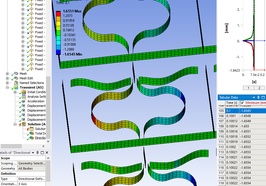
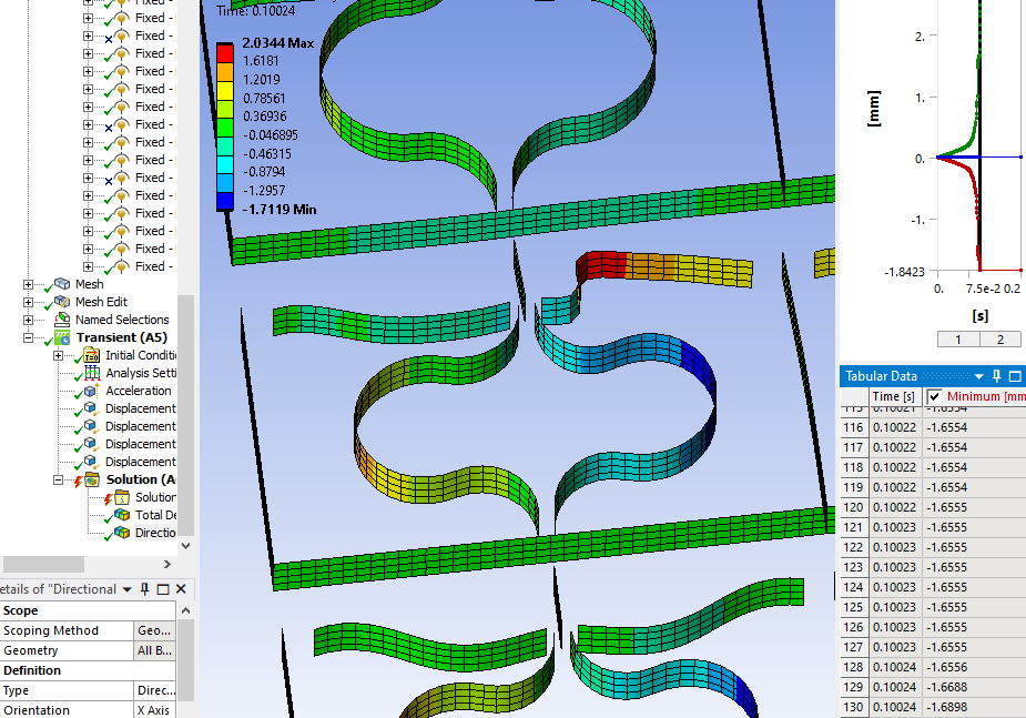 As I said before, if you extrude a deeper structure, 10 or 15 mm instead of only 5 mm deep, that may help to stabilize the structure. You could also increase the thickness of the horizontal springs to reduce the chance of buckling. This is an actual physics result, not an artifact of the simulation.
I increased the horizontal spring by 5% to 0.84 mm and that seems to have fixed the problem. I could get through step 2 with only 100 initial substeps.
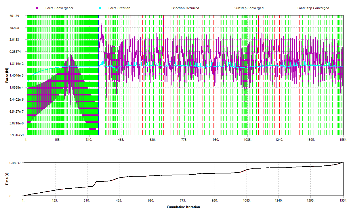 August 16, 2021 at 9:05 pmAugust 17, 2021 at 3:40 am
peteroznewman
SubscriberHere is the F vs D plot where step 1 up to 0.1 s is gravity ramping up while the top rail is held fixed, then step 2 is the bottom rail moving up 30 mm. You can see that about 3 N is perfect force to be in the middle of the flat region.
 Checking the mass, it is at the sweet spot of 0.30 kg.
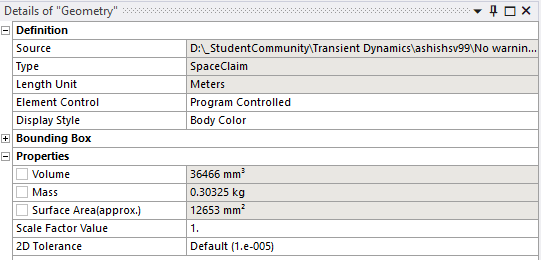 Adjusting the mass up just slightly causes a gravity powered Static Structural solution to shoot well past the middle and end up on the far end of the flat. It is very difficult to adjust the mass to put it on the flat, especially with the wavyness.
To answer your question on Damping, you should watch the videos in this course: /courses/index.php/courses/damping-effects/
August 17, 2021 at 5:43 amashishsv99
SubscriberThank you so much, I will go through it soon.
I actually had a talk with the professor, so he saw all my work and progress and he was appreciating me. But he was not sure if he would take me as an intern as he was like ill have to have experimental knowledge and experience too as there will be such work too during the internship. He said he will let me know his final decision tomorrow that is on wednesday.
August 17, 2021 at 11:48 ampeteroznewman
SubscriberThis professor sounds like he's hiring someone rather than offering an internship, which is supposed to be more about learning and less about working.
Good Luck
Peter
August 21, 2021 at 11:04 amashishsv99
Subscriber
I finally got accepted for the internship. He was scrutinizing so much only because this is the top research institute in the country so he just wanted to make sure he chose the right person, since there will be work involved related to this vibration isolation that I was trying out.
But I am so so happy right now and I thank you so much for the amazing support and help with solving the problem, I don't think I could have done it without you seriously. I really really appreciate it.
I will be looking forward to interact further with you once my internship starts off from Monday onwards if I do face any issues in anything.
Thank You
Ashish
August 21, 2021 at 2:50 pmpeteroznewman
SubscriberCongratulations!
Good luck.
Cheers Peter
August 23, 2021 at 1:20 pmashishsv99
Subscriber
I wanted to ask if you have used ABAQUS software too? My professor is asking me to solve the same thing using ABAQUS right now since they have the license for it, only that will be used. I am not sure about how it can be done using that software.
August 23, 2021 at 6:49 pmpeteroznewman
Subscriber
Why did the professor ask you to build the model in ANSYS if he has a license for ABAQUS? I would love to hear the explanation for that!
I used ABAQUS more than a decade ago. I often build a model in ANSYS and write out an input file for NASTRAN. That works fairly well.
You can write out the input file from Mechanical in a few different formats. Try writing out the file from ANSYS in these three formats: ABAQUS, Ansys and NASTRAN. One of them may import into ABAQUS more cleanly than another.
You can also contact the authors of the paper and ask if they would send you the input deck.
Go find community resources for ABAQUS. I see the ABAQUS Student Edition is limited to 1,000 nodes. Your shell model has 11,500 nodes which exceeds the limit. I suggest you start by learning how to run a simple cantilever beam shell model in ABAQUS.
August 25, 2021 at 3:03 pmashishsv99
SubscriberFirst I was on a probationary period for a month, that is why he was like solve it using any software. Now that this work will be used by them, he needs it to be done using ABAQUS.
Yes I am actually learning ABAQUS now, I feel it is quite similar though a little confusing, it can be done.
I am not sure how to convert ANSYS file into a format for ABAQUS but I will look into it and try it out.
Viewing 176 reply threads- The topic ‘How to perform two step dynamic analysis in Ansys Mechanical’ is closed to new replies.
Innovation SpaceTrending discussionsTop Contributors-
5094
-
1830
-
1387
-
1248
-
1021
Top Rated Tags© 2026 Copyright ANSYS, Inc. All rights reserved.
Ansys does not support the usage of unauthorized Ansys software. Please visit www.ansys.com to obtain an official distribution.
-
The Ansys Learning Forum is a public forum. You are prohibited from providing (i) information that is confidential to You, your employer, or any third party, (ii) Personal Data or individually identifiable health information, (iii) any information that is U.S. Government Classified, Controlled Unclassified Information, International Traffic in Arms Regulators (ITAR) or Export Administration Regulators (EAR) controlled or otherwise have been determined by the United States Government or by a foreign government to require protection against unauthorized disclosure for reasons of national security, or (iv) topics or information restricted by the People's Republic of China data protection and privacy laws.

