TAGGED: constrain-problem
-
-
July 5, 2026 at 2:04 pm
douventzidis
SubscriberHi everyone,
I am trying to numerically reproduce the experiment presented in the attached paper.
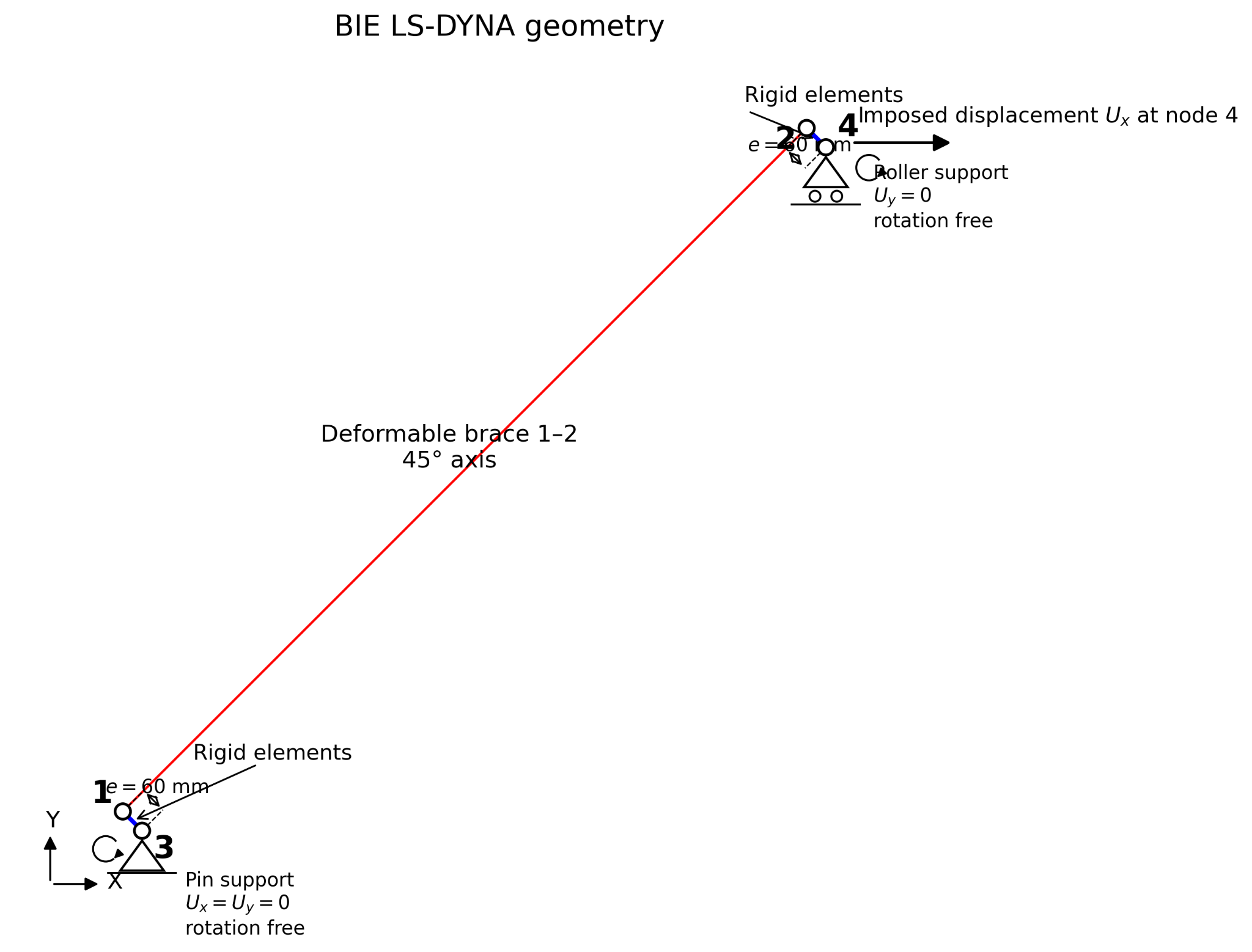
I first modeled the specimen in Abaqus as a 2D model, using constraints to represent the rigid elements. Now I am trying to build the same model in LS-DYNA, but I am having difficulties modeling the rigid elements correctly.
I have tried using *CONSTRAINED_NODAL_RIGID_BODY with pinned supports (free rotation), but the entire assembly behaves as a single rigid body. I also tried modeling the rigid elements with beam elements having a very high stiffness, but the results are still differ significantly from those obtained with Abaqus and the experimental data.
What is the recommended approach in LS-DYNA for modeling rigid elements between two nodes while maintaining pinned boundary conditions? Is *CONSTRAINED_NODAL_RIGID_BODY the appropriate choice, or is there a better approach?
Any suggestions would be greatly appreciated.
-
July 5, 2026 at 5:51 pm
yti2024
SubscriberI don't think you can apply spc's on a Rigid Body node in LS-DYNA. Here is what I suggest you do.
- Create another RB with at least three nodes, say Node 30, 40, and 50, with Node 30 coincident to Node 3, and Node 40 coincident to Node 4, and Node 50 in the direction of travel of the Node 4, but at some distance apart. This RB is the ground, or the foundation.
- Duplicate the Node 50, and add it to the upper RB, (so Node 5 is coincident with Node 50).
- Define a revolute joint using Node 3 and 30 (for 2D problem, or a spherical joint for 3D problem). And Define a translational joint using Nodes 4-40 and 5-50.
The structure now should work as intended.
-
July 5, 2026 at 6:00 pm
yti2024
SubscriberSorry, for the upper joint, it will be a cylindrical joint using two node pairs; this allows sliding and rotation (3D). If you want a translational joint, you need add a third nodal pair to define the direction (out of the plane). (This will limit your problem to 2D). (I am not looking at the manuals, but you get the idea).
-
July 5, 2026 at 6:50 pm
douventzidis
SubscriberThank you very much for your detailed explanation. I really appreciate your help.
I honestly didn’t expect that modelling such a relatively simple structural system would require a completely different approach compared to Abaqus.
I will try your suggestion and report back with the results.
At this stage, I am performing a sensitivity analysis to calibrate the brace model. The next step will be to integrate the brace into a reinforced concrete beam-column frame and evaluate its performance under dynamic loading. Would you recommend following the same joint-based approach for the full structural model as well?
-
July 5, 2026 at 7:25 pm
yti2024
SubscriberSorry I cannot comment on what you should do or not do on your full model becasue I don't have much idea about it. However if you think the deformation of the parts is negligible and the motion of the parts follow strictly as if they are in an FE joint, then I think the RB and Joint is a good simplification of the real problem. In large deformation, these conditions are often hard to meet.
-
July 5, 2026 at 7:56 pm
yti2024
SubscriberFor your original question, if you can, instead of rigid, use elastic material for the two rigid parts, then you can apply spc's on the nodes. Modeling wise, this is easier.
-
July 6, 2026 at 5:46 am
douventzidis
SubscriberI have already checked it.
The main issue is that the force–displacement curve does not match the experimental data, so I am now trying to understand how the model should be calibrated properly.
Anyway, thanks for your time!
-
- You must be logged in to reply to this topic.
-
6825
-
1906
-
1521
-
1343
-
1152
© 2026 Copyright ANSYS, Inc. All rights reserved.