TAGGED: lens, Non-Sequential, projection, Sequential
-
-
October 24, 2025 at 9:45 pm
acc
SubscriberHello Zemax community,
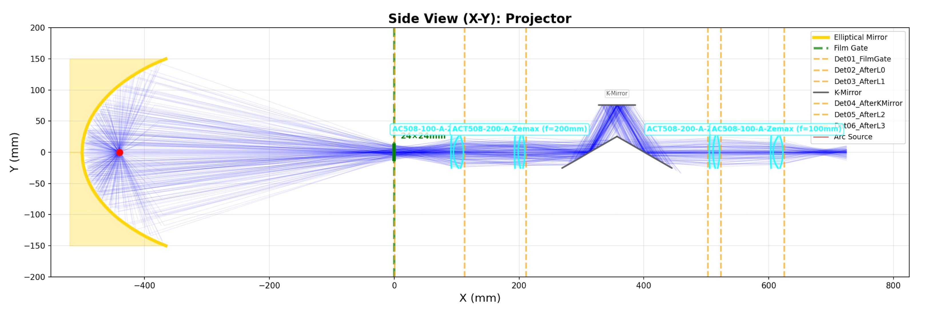
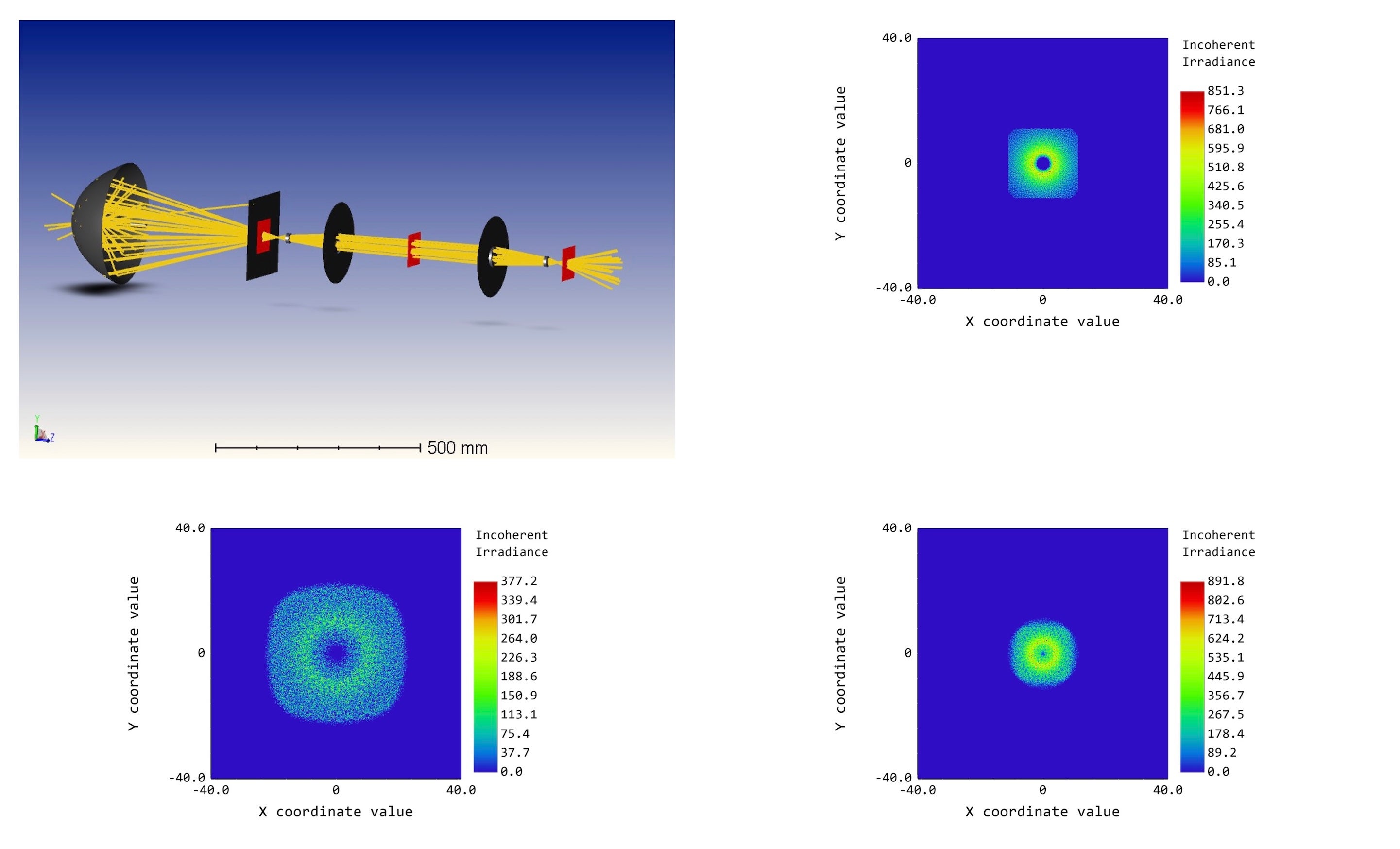
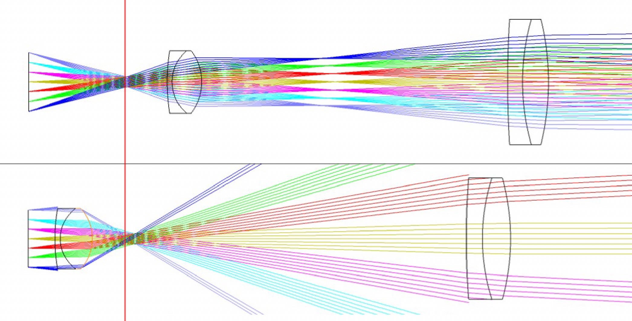
I'm designing a projection lens system for a 35mm film projector and struggling with the correct sequential mode setup for the illumination geometry. The light source is a Xenon short-arc lamp reflected by an ellipsoid mirror, which creates a converging cone with a 40.6 degree full angle that passes through the film gate. The film gate is my object plane, but the light doesn't diverge from it like a typical Lambertian source. Instead, the converging cone from the ellipsoid passes through the film gate, focuses at a point 40mm after the film gate, and then diverges.
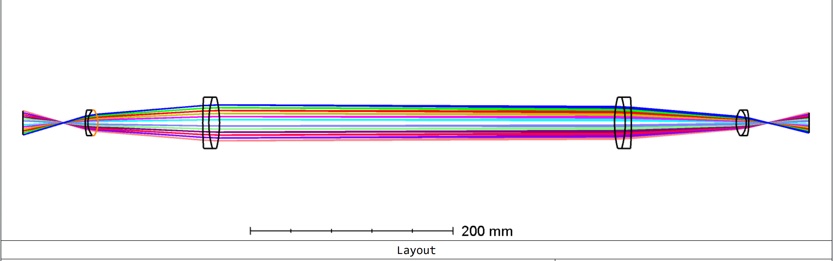
The actual goal is to design a relay system that creates space between the film gate and projection lens for inserting an image rotator, while using standard projection lenses. The key design requirement is that the relayed image at the end must have the same converging cone geometry as the original film gate, so that a standard projection lens can be positioned at the correct distance from the relayed image with optimal light throughput. I need to preserve étendue through this geometry to maintain light throughput, but I'm unsure how to properly set this up in sequential mode to optimize for both relay image quality and throughput simultaneously. I can model the illumination system in non-sequential mode, but I don't know how to approach the combined relay and projection lens design where both imaging performance and étendue conservation are critical.
My current approach is to place the object surface at the film gate with field points defining the 35mm format, then place a stop surface 40mm after the object with a very small semi-diameter of approximately 0.1mm to represent the convergence point. I'm using Float By Stop Size as the aperture type with ray aiming enabled. However, I'm uncertain if this correctly models the converging illumination geometry for sequential mode design purposes, and whether this setup allows me to optimize for both image quality and light throughput.
Film projectors are standard optical systems, so I assume there's an established method I'm missing. Any guidance on the correct sequential mode setup for this Köhler-type illumination geometry would be greatly appreciated. I've attached a visualization of the complete setup showing the ellipsoid mirror, film gate, and convergence geometry.
Thanks!
Paul -
October 30, 2025 at 8:55 am
Niki Papachristou
Forum ModeratorHi Acc,
Thank you for reaching out to us! I think your work is really interesting, I believe that your approach is correct regarding the float by stop choice. Let me reffer to one of our older post responses on a similar question: Design a projection system with two or three lenses, "A projection system is really just an imaging system turned the other way round, so the object conjugate is a short distance from the lens and the image conjugate is a long distance. Other than that, it’s not really fundamentally different to any other imaging system. I’d recommend using Object Height as the feild definition, and float-by-stop as the aperture definition. Use the Optimization Wizard with whatever criterion you’ll use to measure performance, and a REAY operand to set the image size. You will probably need to turn ray-aiming on as well, if the stop is buried somewhere inside the system as it usually is."
Regarding your question for additional refferences I would recommend the: Projectors Part 2: Projection Lens and Introduction to illumination systems (Köhler illumination).
I hope that was helpful.
Kind Regards,
Niki
-
October 30, 2025 at 1:43 pm
acc
SubscriberHey Niki,
thank you for your response! I will look into the links again (already came across them before), but my main issue is that I don't think the float-by-stop as the aperture definition works to simulate my case. It seems to work when the first lens comes after the STOP. However, as the f2 of the ellipsoid reflector, i.e. the focus of the illumination beam needs to be in the entrance pupil of the projection lens/relay assembly, the first surface is before the STOP. And this results in a different cone shape, therefore defeats the whole purpose of simulating it with the float-by-stop as aperture?Â
I visualized it with the graphic below, where the read line is the STOP at z=40. The second version has the same float-by-stop but a completely wrong illumination cone..
I really don't know where to look further into this.Â
Â
-
November 11, 2025 at 10:25 am
Niki Papachristou
Forum ModeratorHi acc,
Since the float by stop does not work for you on your second case, have you tried to create a STOP surface and specify its location so to create the cone angle that reaches yhe second lens?
Kind Regards,
Niki
-
- You must be logged in to reply to this topic.
-
6369
-
1906
-
1457
-
1308
-
1022
© 2026 Copyright ANSYS, Inc. All rights reserved.


