TAGGED: hfss, permanent-magnet
-
-
August 31, 2023 at 8:44 pm
Andrew Walsten
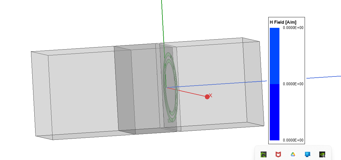
SubscriberI am trying to simulate a split-ring resonator with a uniform static magnetic field being applied to it. I start by creating a ferrite material where I assign some value for the magnetic saturation. I end up with a geometry like the one below. The two large boxes on either end are vacuum and have radiation boundaries assigned to their faces. The rings and the square behind them have a perfect e boundary applied to them. I have a lumped port excitation on the SRR. The ferrite material is the slighlty larger box behind the SRR. It has a magnetic bias excitation applied to it. I assign an internal bias to it and then give it a value for the permeability tensor rotation. After I run the simulation, I am getting no magnetic field from the ferrite material. Can someone explain to me what I am doing wrong? Also, I wasn't sure how the permeabiltiy tensor rotation affected the direction of the magnetic field. I figured I would mess around with it and figure it out, but if someone knows and wants to save me some time that would be amazing. There are a x, y, and z angle for it. I would appreciate any help.
-
September 5, 2023 at 10:51 pm
Faezeh Ladani
Ansys EmployeeHi Andrew,
There is an open example in HFSS on Ferrite circulator (both uniform and non-uniform magnetic bias). From menue go to File>Open Examples...>HFSS>RF Microwave>Ferrite_Circulator.
I suggest you first go over that example and check your settings accordingly.
Also, please review the help document on "Ferrite Permeability Tensor in HFSS" to double check your setting. You may search for this keyword in HFSS online help.
Also, instead of creating two separate airbox at the two end, delete them both... Then right click in the modeler window, Create Open Region. Select Rad boundary (which is the default), select the x and y paddings to 0, and in +z and -z, you may assign it accordingly.
If this does not fix the issue, please create a suppoert request through customer portal to investigate the design file.
-
September 11, 2023 at 5:25 pm
Andrew Walsten
SubscriberHi Faezeh,
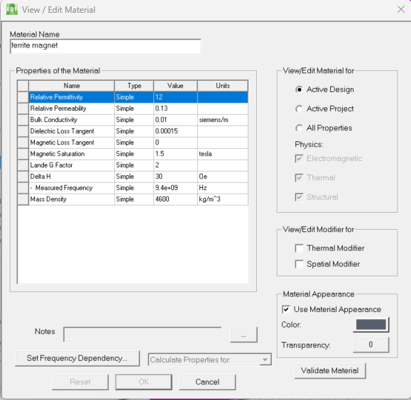
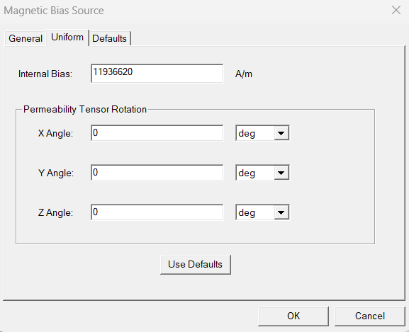
Thank you. That helped some. I changed the properties to be more similar to the example. I also moved the ferrite material back a little bit so that it wasn't touching the ground plane as that is more similar to my actual experimental setup. The ferrite material now has an organized mageneti field; however, it is just organizing based off of the magnetic field of the SRR. I need it to behave as a permanent magnet. I have attached images showing my material properties for the ferrite and the magnetic bias setup. I believe I have it setup correctly, but are there any obvious errors you see? I want the ferrite "permanent magnet" to have a field in the z+ direction.
-
-
September 20, 2023 at 10:07 pm
Irina G.
Ansys EmployeeHi Andrew,
I don't see anything illigal with the material definition. I am surprised with permeability much less than 1, but with non-zero MS value, the permeability is overridden with the Ferrite Permeability Tensor based on Polder model. Search "Ferrite Permeability Tensor" in on-line HFSS Help for detailed formulas. Magnetic Bias source as shown is set to be along Z axis.
Note that when you plot H-field in HFSS, you don't plot DC external field but RF H-field. HFSS solves for E-field (as complex vector) and then deribes H-field based on Maxwell eqs. and solved E-field.
If you still think that RF H-field is too small, see that the power is actually entering the design. How S-parameters look like? Can you plot E-field? Is it as expected?
-
September 20, 2023 at 10:38 pm
Faezeh Ladani
Ansys EmployeeHi Andrew,
Irina has provided great information about overall approach for this simulation. Specific to permanent magnet, to define the ferrite as permanent magnet in HFSS, the magnetic bias we use is a link from Maxwell (where you can define magnetic coersivity). The Circulator example I mentioned in my previous response includes that as well. Please review the example as well as the help document that comes with it, especially go through the Non-Uniform Bias. Design 02_hmag and Design 03_FCNonUniform are related to that.
Note that in Maxwell, besides this B-H curve, there is option of Magnetic Coercivity vector (which you define it along z). Check the material definitions that are used in the example.
-
October 3, 2023 at 5:34 pm
Andrew Walsten
SubscriberHi Faezeh,
I have gone through the example and it honestly is not helping much. It pretty much just has the entire thing setup already with a list of properties and stuff, but with no description of how to get everything to that point. If ANSYS would create step-by-step tutorials to go with the examples, I feel like it would be way more helpful for people such as myself that aren't as experienced with ANSYS.
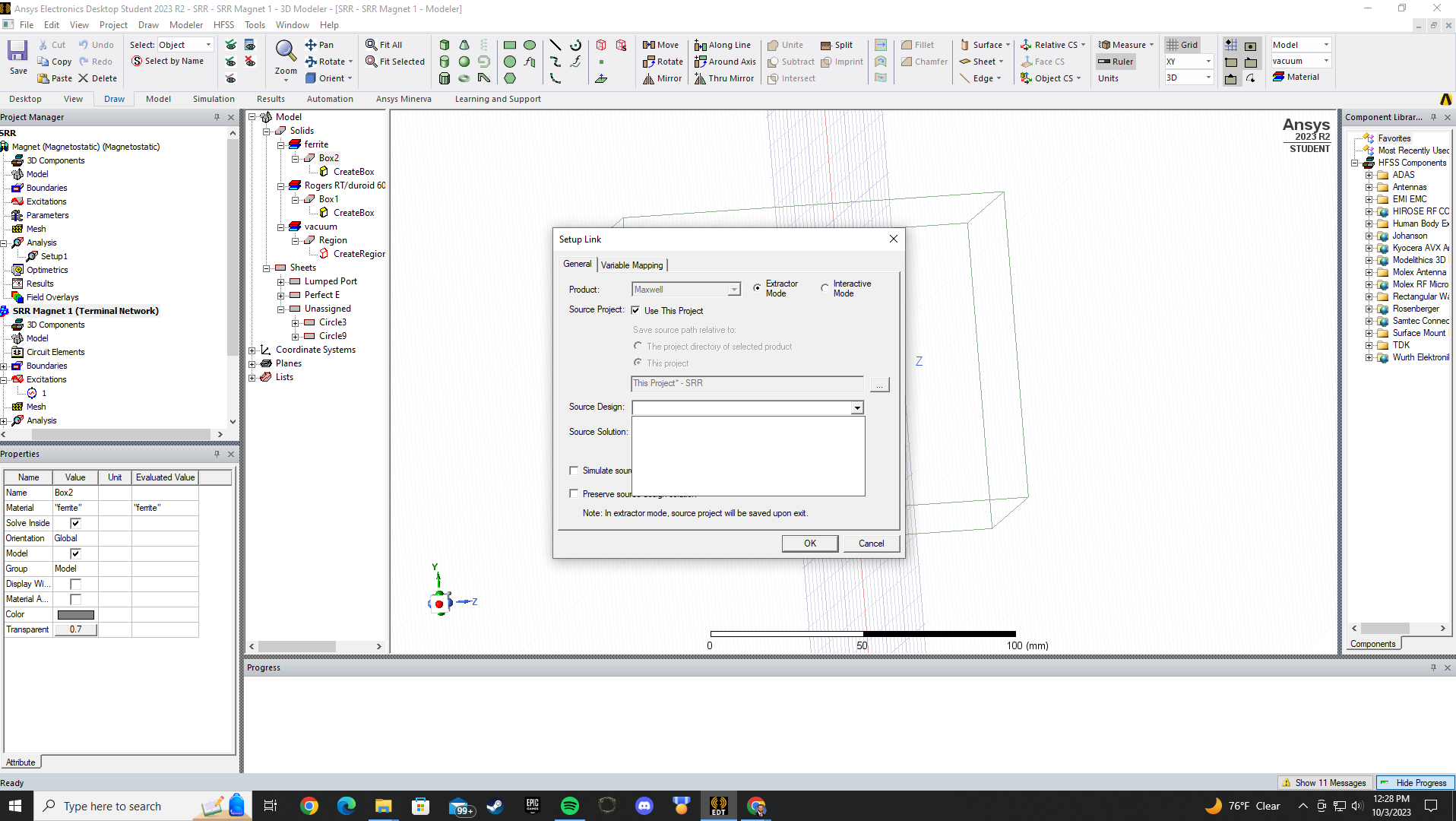
That said, I was able to piece together some things from the example and what you said above. If I am understanding correctly, I need to run Maxwell with the permanent magnet and then use the results from that in Setup Link to provide the information for the ferrite in HFSS. However, Setup Link is not allowing me to do that. I'm going to walk through what I am doing. Can you tell me where I am going wrong?
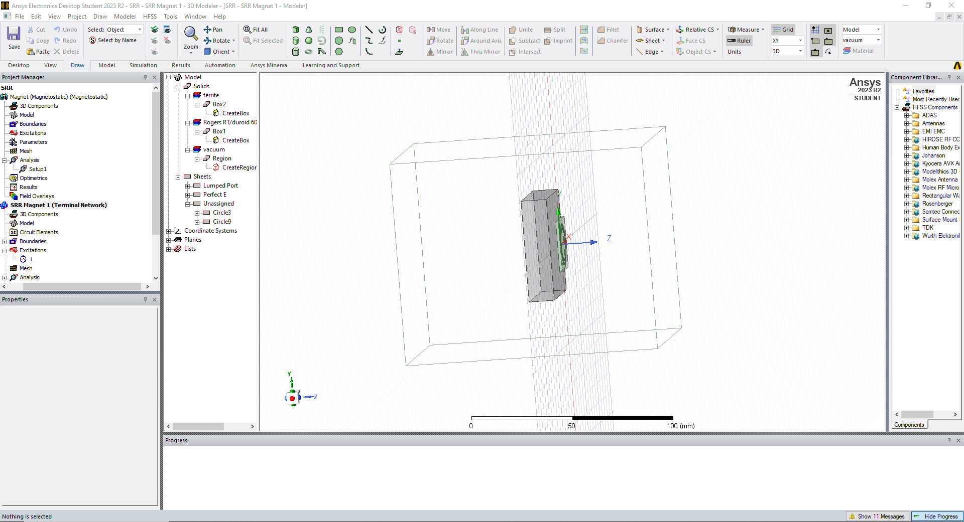
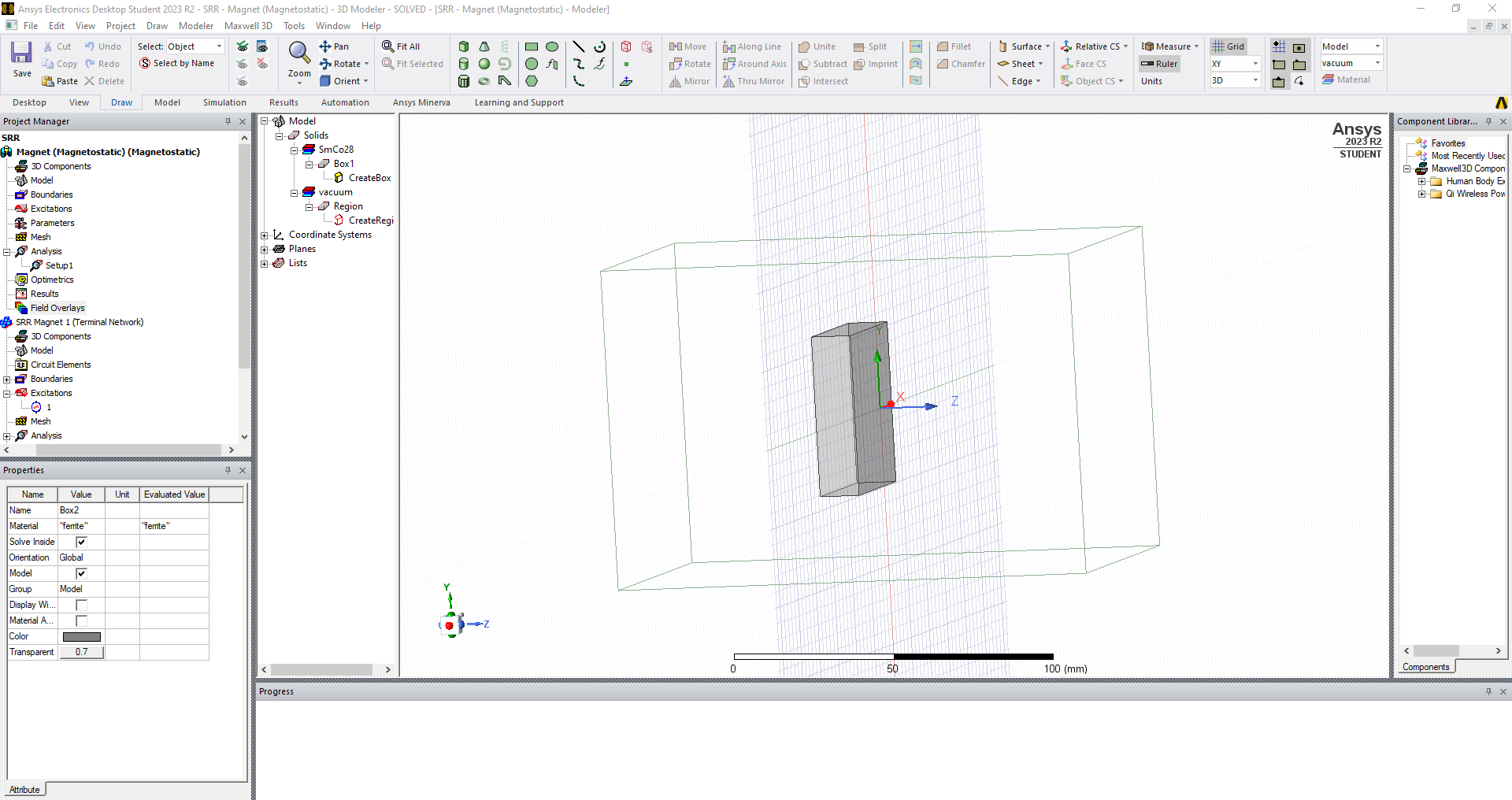
I create the SRR and ferrite block as shown below. I assign my boundaries and the lumped port excitation. Then, I go up to the taskbar and select Project > Insert Maxwell 3D Design. I then use this to create the exact same block geometry again, but I assign the SmCo28 material. I set up my properties so that the magnet is pointing in the direction I want. I run Maxwell and it solves the setup. Then, I go back to the HFSS setup and click on the ferrite box. I go to Assign Excitations and choose Magnetic Bias. I choose Non-Uniform and it automatically goes to Setup Link. I select Use this Project as the Source Project. When, I select Source Design and Source Solution, there are no options unlike with the Ferrite Circulator Example.
-
-
- The topic ‘How to Make a Uniform Magnetic Field in HFSS Using Magnetic Bias’ is closed to new replies.


-
3387
-
1052
-
1050
-
886
-
852

© 2025 Copyright ANSYS, Inc. All rights reserved.

