Hello everyone,
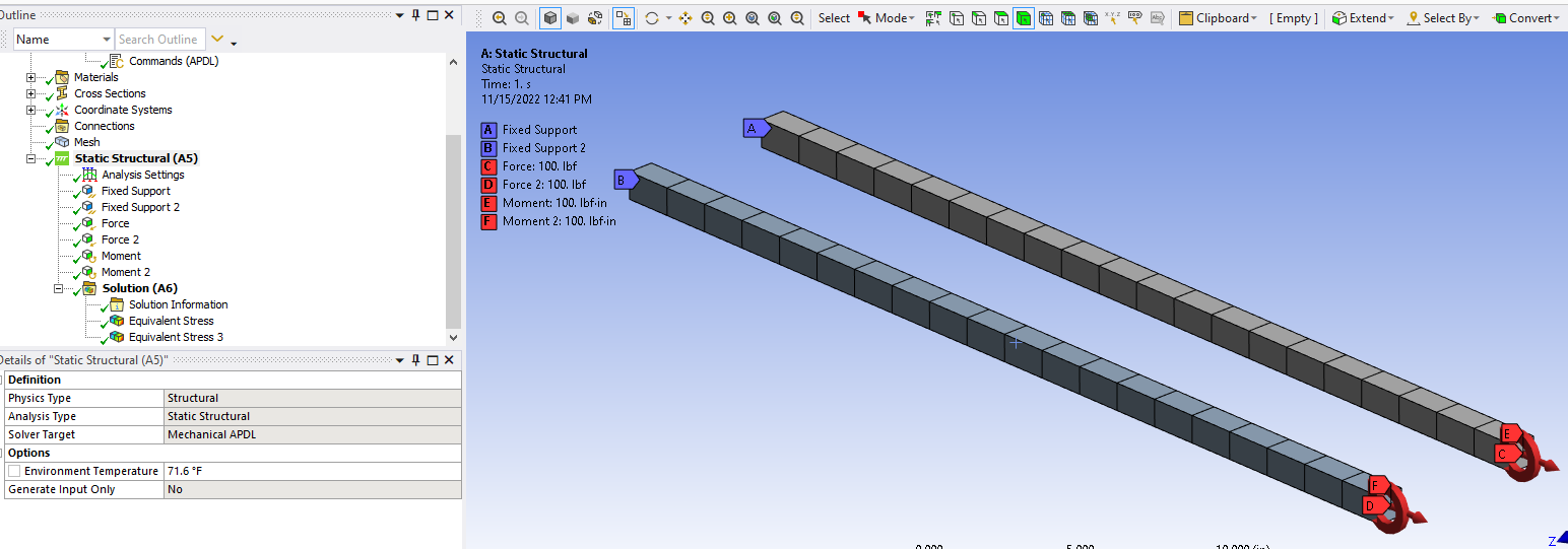
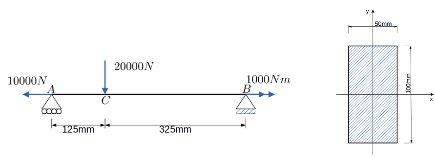
I know that it is possible to add more cells to beam element's (for example BEAM188 or BEAM189) cross-section with SECDATA command, but after using SECDATA the results of the calculation is nonsence. For example when using rectangular cross-section for beam element the default cell count along width and height is 2 ---> "SECDATA,50,100,2,2".
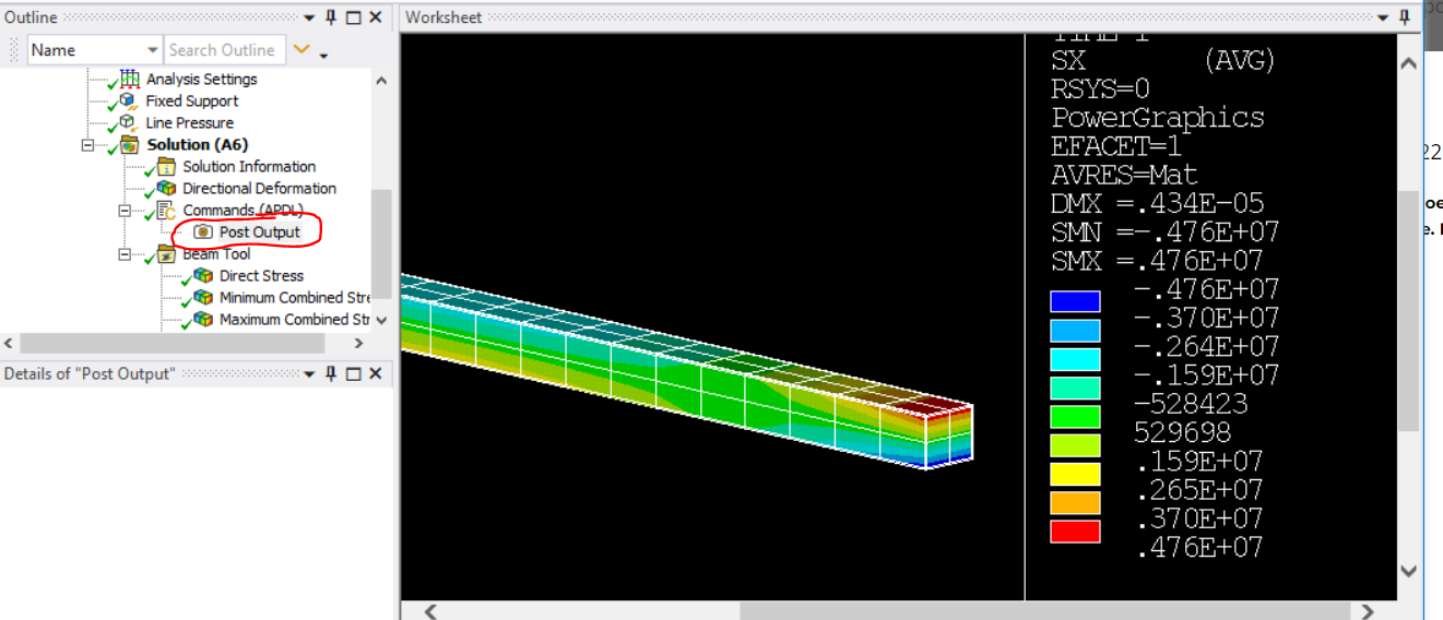
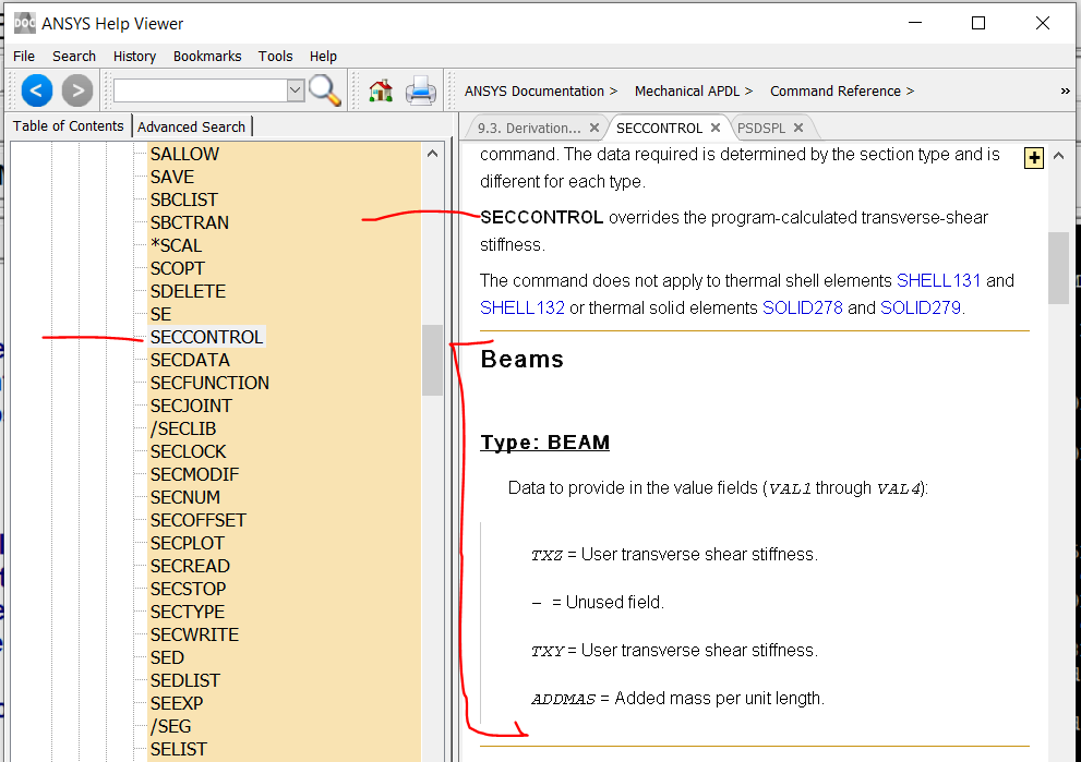
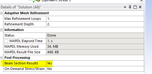
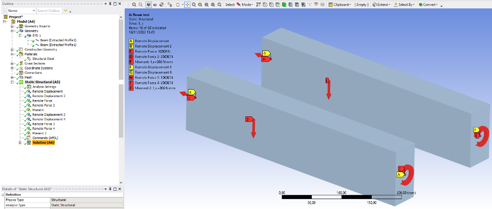
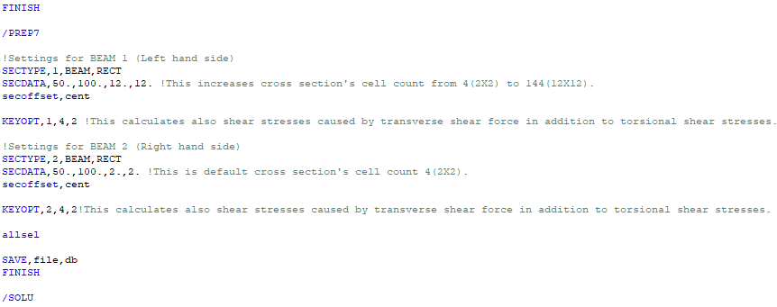
I have added APDL commands object under static structural to increase cross-section's cell count from 4(2X2) to 36(6X6) and also taking account warping and shear stresses from transverse shearing with following content:
---
FINISH
/PREP7
SECTYPE,1,BEAM,RECT
SECDATA,50.,100.,6.,6.
secoffset,cent
KEYOPT,1,1,1
KEYOPT,1,4,2
allsel
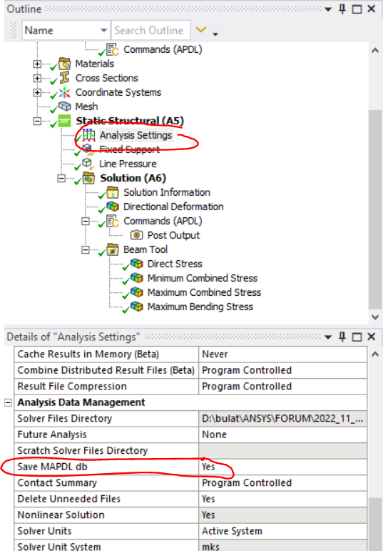
SAVE,file,db
FINISH
/SOLU
---
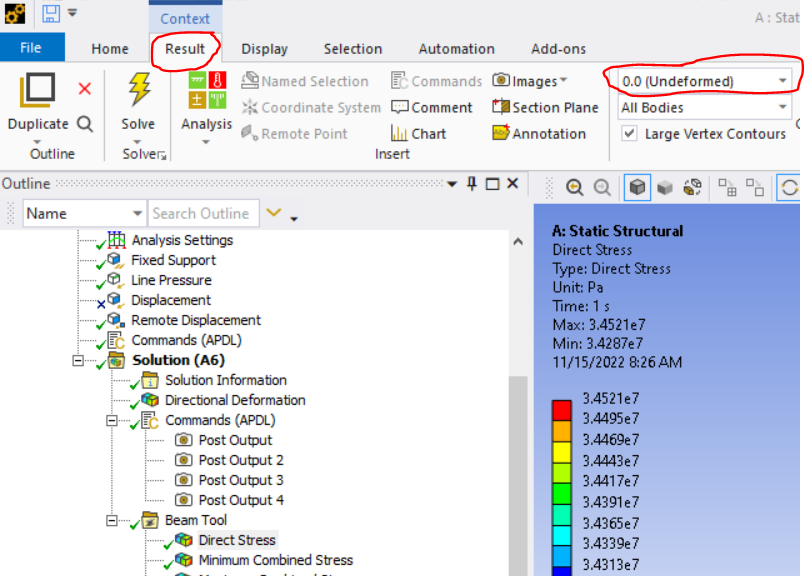
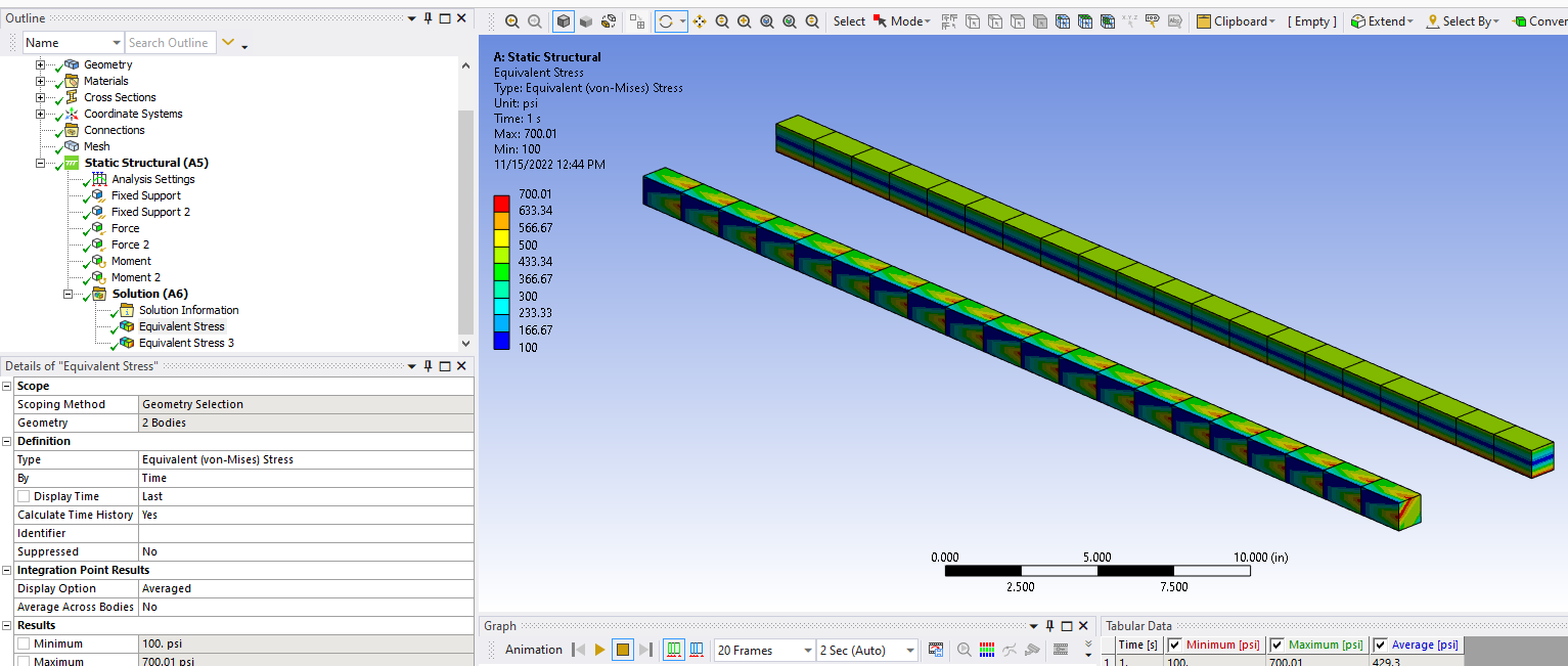
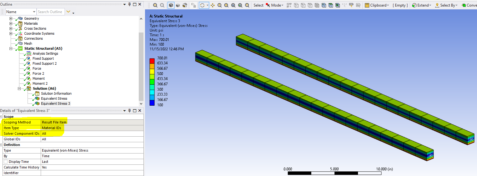
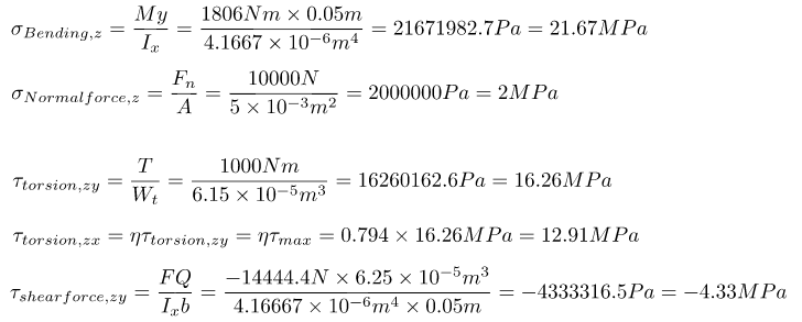
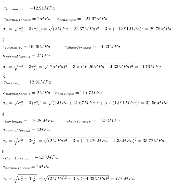
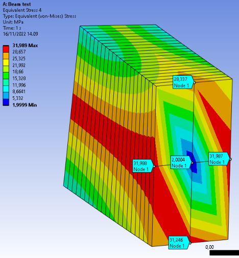
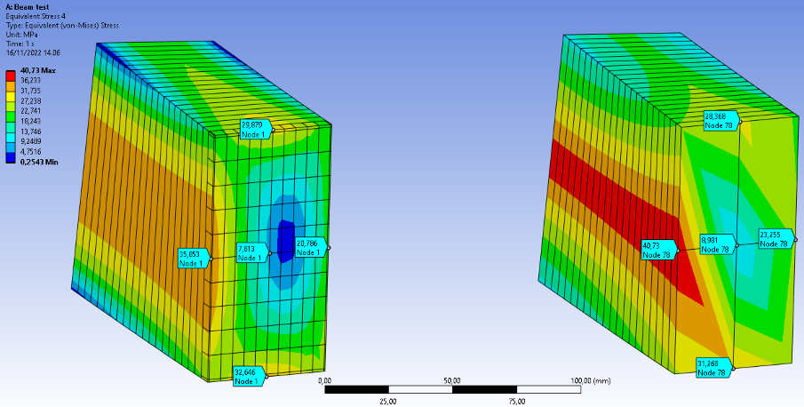
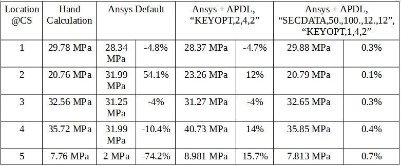
I think that this command object adds the cross-sectional cells, but when post-processing for example the von Mises stress results, they are nonsense... What I'm doing wrong, should the beam be remeshed in some way to add the additional cell points ?
Another interesting thing is that why beam188 and beam189 elements doesn't take in account flexure-related shear stresses in addition to shear stresses caused by torsion by default ---> KEYOPT,N,4,2 ? By default beam elements calculates only shear stresses caused by torsion --->KEYOPT,N,4,0. I think that this kind of default setting might be quite dangerous in some scenarios.
Best regards,
Pirelli93