TAGGED: interconnect, Photodetector, spectrum
-
-
December 10, 2024 at 2:44 pm
m.belchovski
SubscriberHi,
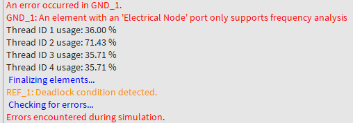
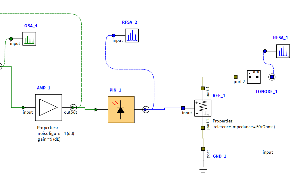
I want the PD that I am using to have a 50 Ohms impedance because I want to read out on the elecrical spectrum analyzer the power with an impedance of 50 Ohms. How can I implement that? In the figure attached here I try to implement a resistor, in that case I cannot simulate in the time domain. In this case I get the following errors:
Do you have any other solutions or suggestions? Thanks
-
December 10, 2024 at 9:57 pm
Kyle
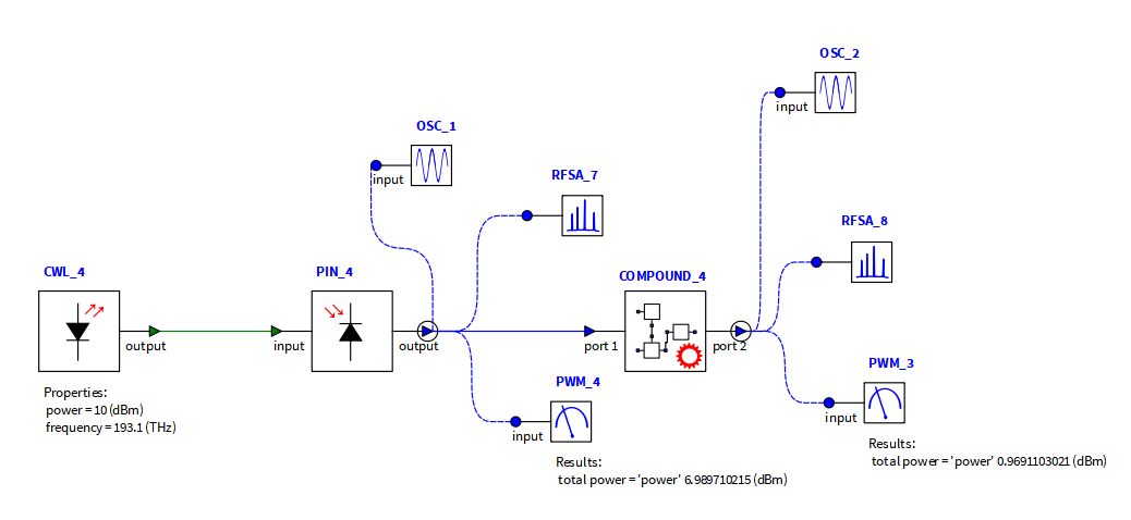
Ansys EmployeeHello, for time domain simulations the electrical linear elements must be placed inside a Compound Element with its “scattering data analysis” set to “true”. INTERCONNECT will then calculate the S-parameters of the circuit, and use them in the simulation. There are a couple of examples of this here: Electrical Linear circuits – Ansys Optics
The electrical signal output of the PD element is a current, so it should be connected to a Current Source electrical linear element inside the compound element. Then connect this to the load Resistor, with a Voltmeter measuring the voltage across the resistor, like in the RC circuit example on the Electrical Linear circuits page.
-
December 11, 2024 at 2:40 pm
m.belchovski
SubscriberHi Kyle,
Thanks a lot for the clarification. I have a follow up question. I want to measure the power spectrum of the output, however in the Spectrum Analyzer I do not see the option to show the power at 50 Ohms termination? The power meter is adjusted to show power at 50 Ohms from a voltage signal. But the spectrum analyzer does not have the option? Do you have a workaround for this problem? Thanks a lot once again.
-
-
December 11, 2024 at 8:57 pm
Kyle
Ansys EmployeeThe RFSA uses a default impedance of 1 Ohm for the power calculation, and unlike the PWM there is no option to change this. You can submit a feature request for this if you like at this link: https://ix.lumerical.com/
As a workaround, to get the results for 50 Ohms you can divide the power result of the RFSA (in Watts) by 50. You can do this in a post-processing script, or you could add an Electrical Constant Multiplier element in front of the RFSA with a gain of 1/sqrt(50) to renormalize the amplitude of the signal before the RFSA.
-
- You must be logged in to reply to this topic.


-
4703
-
1565
-
1386
-
1242
-
1021

© 2025 Copyright ANSYS, Inc. All rights reserved.


