
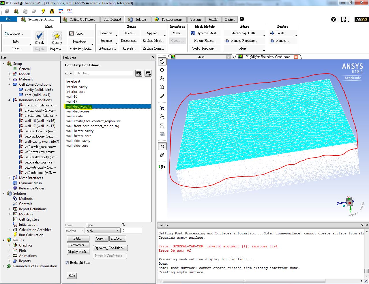
How to highlight and know more about automatically generated boundary condition?


Viewing 7 reply threads
- The topic ‘How to highlight and know more about automatically generated boundary condition?’ is closed to new replies.


