TAGGED: 3d-geomertry, extrude, Fluid Volume, meshing
-
-
December 6, 2023 at 7:30 am
hasan.mustafa.moayad
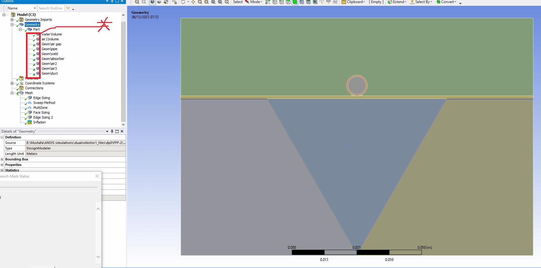
SubscriberHello everyone, I'm a beginner in ANSYS Fluent and I'm working on solar thermal collectors.I drew the geometry to have these (9) parts: (air gap, pipe, water volume, weld joint, absorber, air duct, and 3-air domains) as shown in the picture below. Also, I made these parts as one part (form a new part).In meshing, I generated the mesh directly after that I began to modify it by trying several options (sizing, inflation,...., etc.) as you can see in the picture. But, still can't reach so good mesh quality (skewness & orthogonal).My questions are:1- regarding the geometry, is there any difference if I make an extrude for a surface to create a fluid domain? or should all fluid domains created by making volumes?2- regarding the mesh, the tick sign in front of the geometry parts (see the red rectangle in the picture) is changing every time I make meshing, what is the reason?3- I'm asking you to help me do the best mesh for my case. Which mesh method and sizing should I select to enhance the mesh? -
December 6, 2023 at 11:51 am
CFD_Friend
Ansys EmployeeHi Mustafa,
i) Fluid zones should be either a surface (if the problem is 2D) or 3D volume (if it's a 3D problem). 3D volumes can be created from extruding 2D surfaces, if that answers your question.
ii) The double tick sign means the mesh has been created on the part, and if its only a single tick, the mesh has not been created on it.
iii) Please go through the meshing user guide for help with any meshing-related queries. Here is the link: Meshing User's Guide (ansys.com)
-
December 6, 2023 at 2:11 pm
hasan.mustafa.moayad
SubscriberDear CFD-Friend, thank you for your valuable reply.
i)I'm dealing with a 3D case, and as you can see in the previous picture I have 5 fluid domains, two of them named as (water and air1) which have been created by using the space claim editor (Prepare ----- Volume Extract) tool. The other 3 domains are created through (Design ---- Pull) tool.
My question: Is the followed procedure right to create the fluid domains? I mean is there any difference if I used (The volume Extract tool or Pull tool) to create the fluid domains? or do I need to create the fluid domains by using (Volume Extract) tool only?
ii) It's so clear.
iii) I'll do my best.
-
December 6, 2023 at 2:22 pm
CFD_Friend
Ansys EmployeeHi Mustafa,
Yes, the approach followed is right. Both approaches can be used to create a fluid zone.
-
- The topic ‘How to get good mesh quality’ is closed to new replies.


-
3432
-
1057
-
1051
-
896
-
892

© 2025 Copyright ANSYS, Inc. All rights reserved.


