TAGGED: ansys-apdl, ansys-mechanical, ansys-mechanical-apdl
-
-
July 8, 2023 at 9:32 am
Ding yuhang
SubscriberHello,
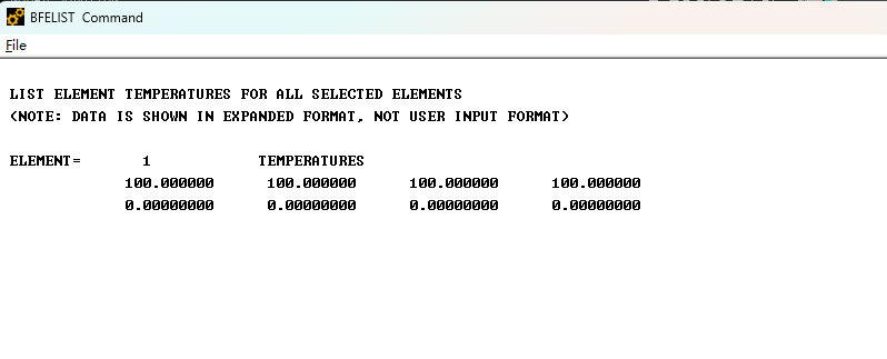
I want to define temerature graident through one shell elelemt thickness(shell181), so i tried to input 8 temperatures in the layer(4 temperatures for bottom and 4 temperatures for top ) of the element's corners through the command "BFE,all, temp,STLOC,%tabname%".
However, when i checked the BFLIST output,only the first temperature in the table was used for bottom of the layer(see figure below).
So i think it may be the wrong table defination with "*dim" commands?
Here are commands
/clear,all
/prep7
et,1,shell181
mp,ex,1,2.1e11mp,prxy,1,0.3mp,alpx,1,1.0e-5sectype,1,shellsecdata,1,1,,,1blc4,0,0,10,10esize,,1aatt,1,,1,,1amesh,alltunif,0*dim,tem,table,8,,,tem(1)=100,100,100,100,50,50,50,50bfe,all,temp,,%tem%Dk,all,ux,0, , , , uy, uz, rotx, roty,rotz/soluanty,staticoutres,all,allsolve/POST1set,lastPLNSOL,BFE,TEMPPrNSOL,BFE,TEMPBFELISTMany thanks in advance.
Best regards.
-
July 10, 2023 at 1:02 pm
Ashish Khemka
Forum ModeratorHi,
You can use SHELL 131 to model linear variation of temperature between top and bottom layers
Regards,
Ashish Khemka
-
July 10, 2023 at 1:50 pm
Ding yuhang
SubscriberDear Ashish Khemka,
Thanks for your reply, does this mean that I need to do a thermo-mechanical coupling analysis??
Best regards.
-
-
July 10, 2023 at 4:06 pm
Ashish Khemka
Forum ModeratorHi,
For thermal analysis, by default, for shell elements, we cannot give different temperatures for top and bottom (i.e. temperature is constant throughout the thickness of the shell). But, this can be done by changing keyoptions of the shell131 element which indirectly creates two new dofs (say for a shell of 1 layer) TTOP & TBOT. Then further commands are necessary to apply temperatures on these newly created dofs via D command (say, D,all,TTOP,100 - applies temperature of 100 on all nodes of the top surface).
Also, this can be done in Mechanical as well: How can we apply different loading conditions on both the top and bottom of a shell/surface body, e.g., temperature on top face and convection on bottom face. - Ansys Knowledge
Please see if this helps.
Regards,
Ashish Khemka
-
July 12, 2023 at 9:26 am
Ding yuhang
SubscriberDear Ashish Khemka,
This is very helpful to me, thank you for your reply.
Best regards.
-
- The topic ‘How to define the table when using BFE commands?’ is closed to new replies.


-
3487
-
1057
-
1051
-
945
-
917

© 2025 Copyright ANSYS, Inc. All rights reserved.


