-
-
May 29, 2021 at 2:24 am
muqing114
SubscriberHello everyone,
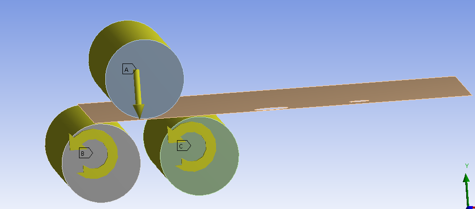
I am Qing.I want to simulate a cylinder made from steel plate by a three-roller bending machine as image 1.I know it is a plastic forming process.I have some questions to consult:
1、which module can i use to complete the simulation,Transient structural or Explicit dynamics?I checked some papers both methods are used to simulation a plastic forming process.
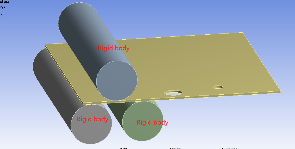
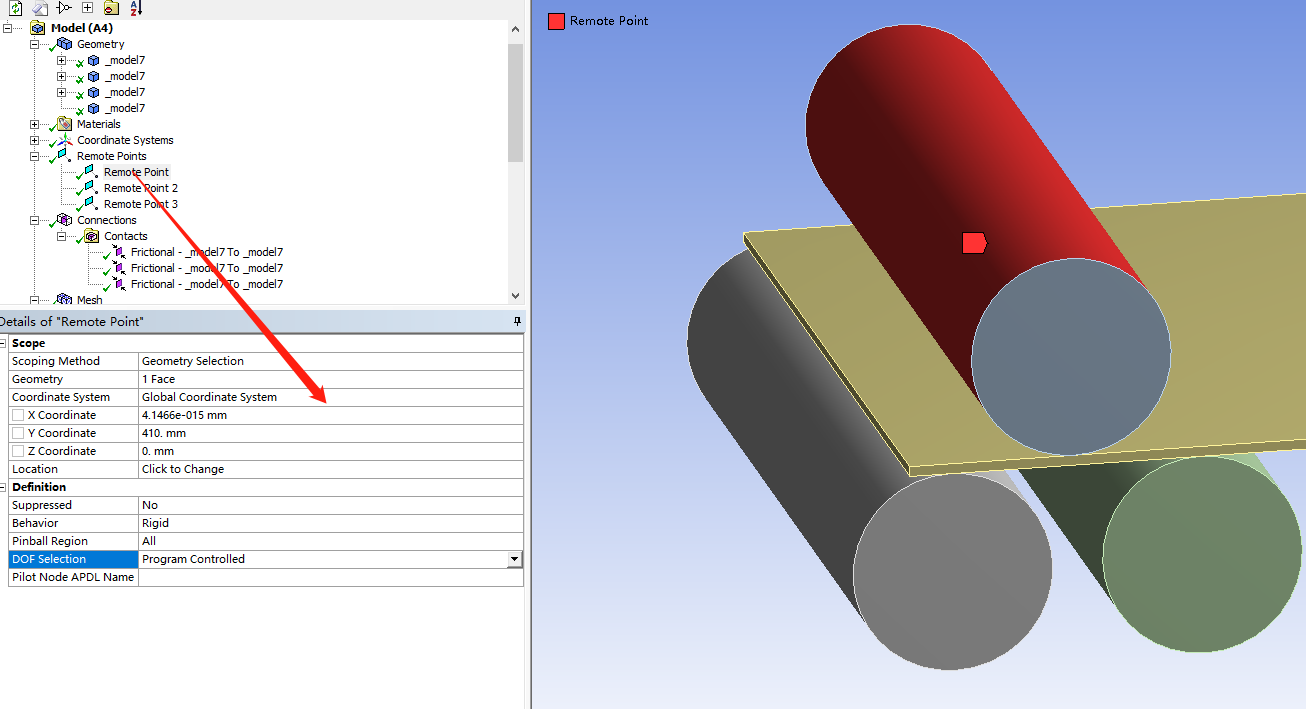
2、When i simulate this processwith Explicit dynamics, I set a Remote displacement on the top roll with Y-displacement(as image 2) and Z -Ratation free .when i set the top roll move speed (Every 0.5 second, the Y axis moves 1.5 mm)according to the real value ,the time spend is too long;finally, i set every 0.005 seconds, the Y axis moves 1.5 mm,the real speed is 300mm/s?how to simulate the real speed in Explicit dynamics?
May 29, 2021 at 4:24 pmpeteroznewman
SubscriberHello Qing Dynamics solvers are used when inertial forces are a significant portion of the internal forces caused by deformation. Rolling is a low speed process so the inertial forces are insignificant. That means you could solve this problem using the Static Structural solver.
The Static Structural solver permits you to apply rotations to rollers and move a sheet through the roller system. Though time is used in Static Structural, it is only used to keep track of load increments and so is arbitrary and by default, each step is 1 second in a multistep solution.
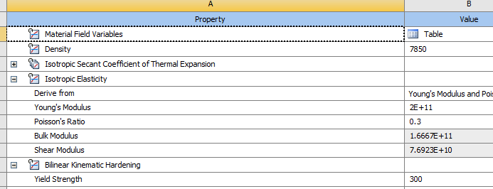
The most important feature to include in your simulation is Plasticity in the Material model. The simplest plasticity material model is Bilinear Kinematic Hardening.
The benefit of Explicit Dynamics over implicit solvers such as Static or Transient Structural is that the contact algorithm is very robust. However, this sheet rolling problem is not too difficult and can be made to work in Static Structural.
The problem with Explicit Dynamics is the very tiny time steps it is required to take. The time step is dictated by the materials and the smallest element in the whole model. The way to reduce your wait time is to move things faster than in real life, but not so fast that the inertia forces start to become significant.
I recommend you start with Static Structural. Make the roller bodies have a Stiffness Behavior of Rigid. Put 8 linear elements through the thickness of the sheet. Try a 2D plane strain model as that will solve very fast if you can get the boundary conditions the way you need them. For a 2D model, you need surfaces in the XY plane.
May 31, 2021 at 6:52 amSubscriberJune 3, 2021 at 7:35 amsantiagosep1706
Subscriber, when you spoke about to "move things faster than in real life", in the practice what implication does this consideration.ie what change in ansys analysis settings?
June 3, 2021 at 1:35 pmSubscriberIf the real speed is 0.3 m/s then in the analysis you could set the velocity of a component to be 3 m/s to get a 10x speed increase in the simulation. If the purpose of the analysis was to see 300 mm of motion, then instead of using an End Time of 1 second, you would use an end time of 0.1 second and that would take only 1/10 of the waiting time for the Explicit Dynamics solver to finish than using an End Time of 1 second.
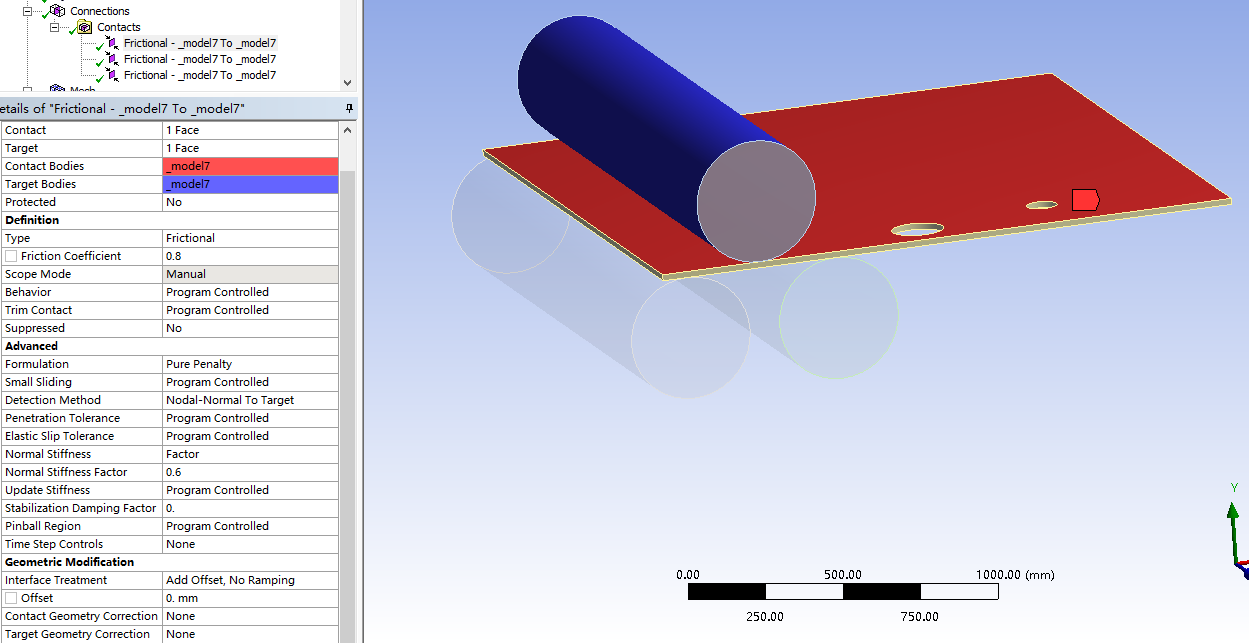
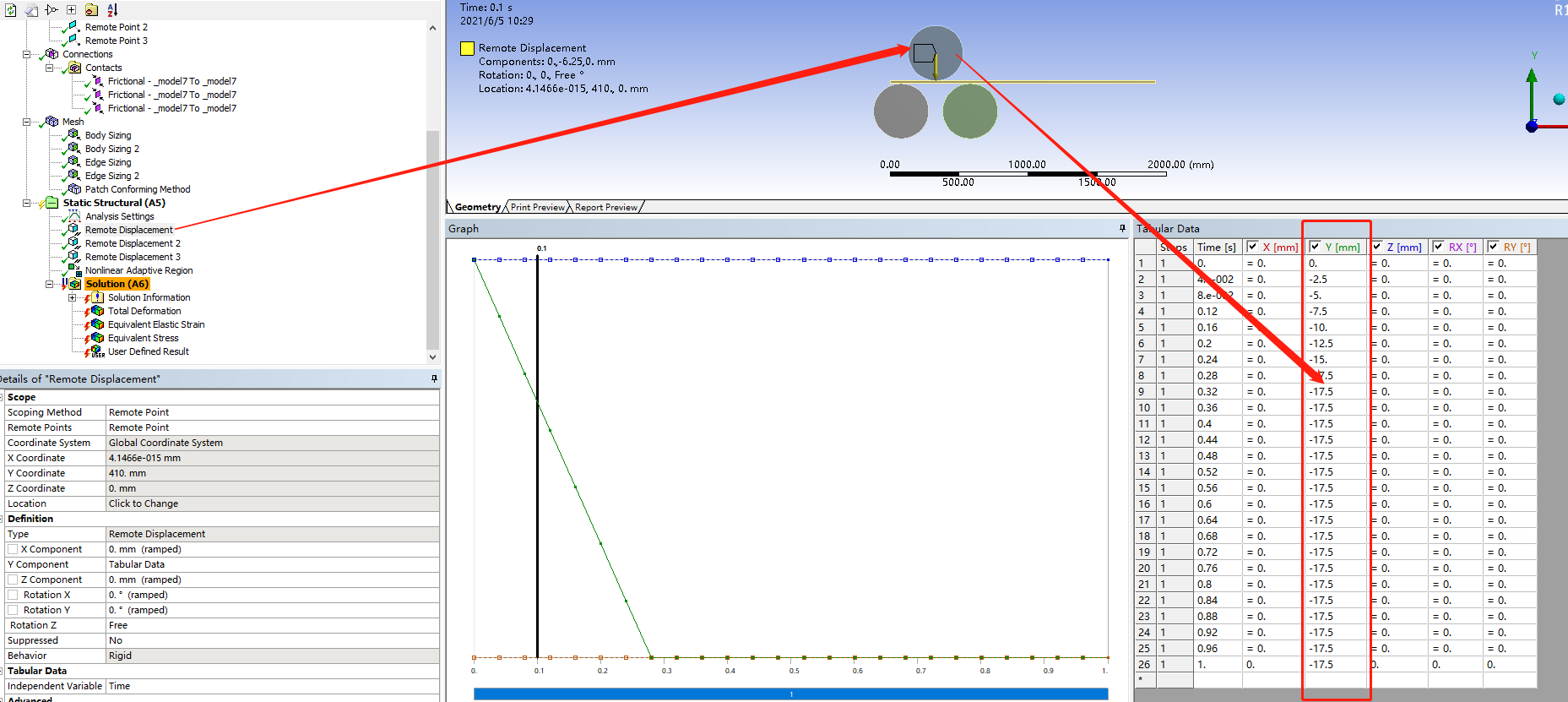
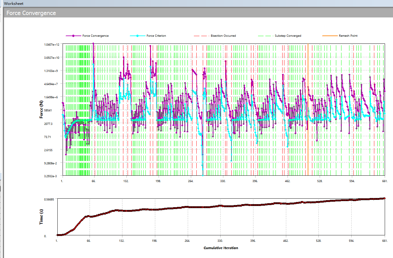
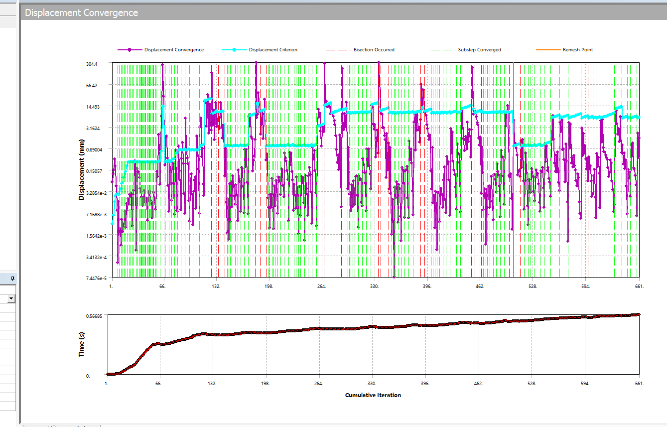
June 5, 2021 at 2:48 amSubscriberHello @peteroznewman ´╝îCan you give me some suggestions about how to get Force Convergence with Static Structural? I have tried many times´╝î failed for this reason every time.Here are my settings for the simulation:
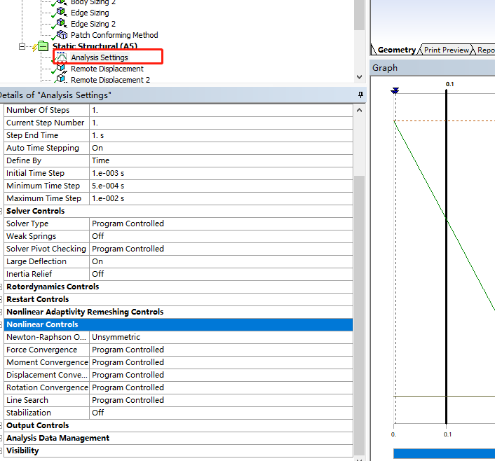
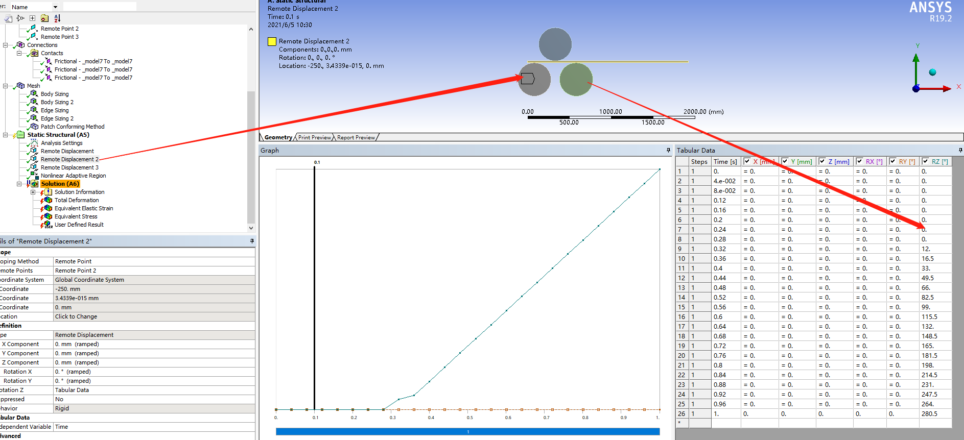
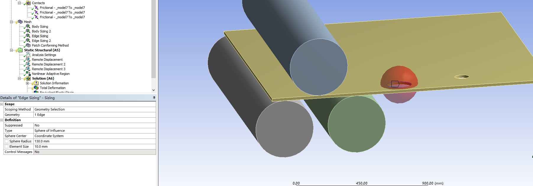
June 5, 2021 at 5:52 pmSubscriberHello Qing How many elements are meshed through the thickness? There should be at least four and better to be eight linear elements.
What version of Ansys are you using?
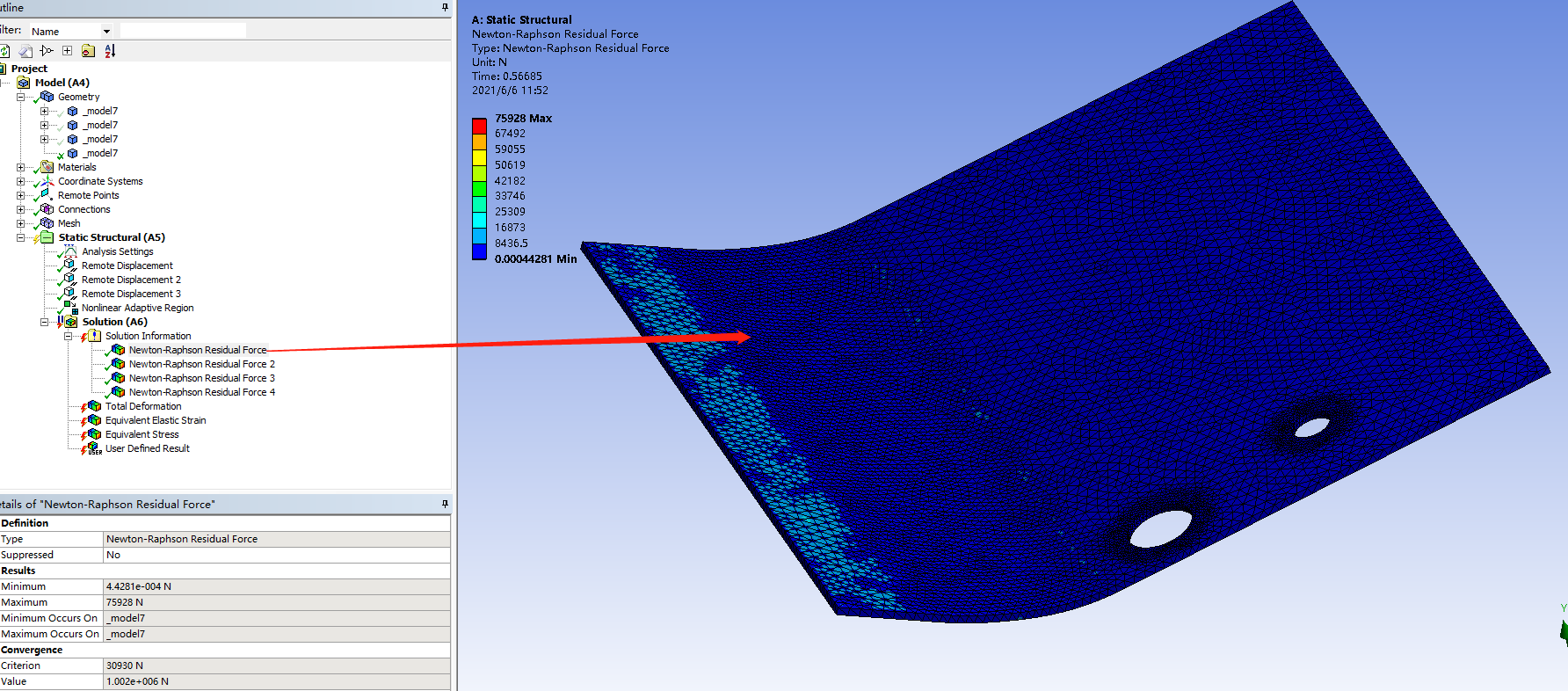
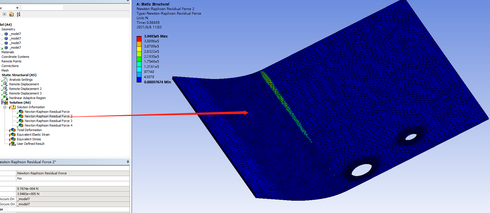
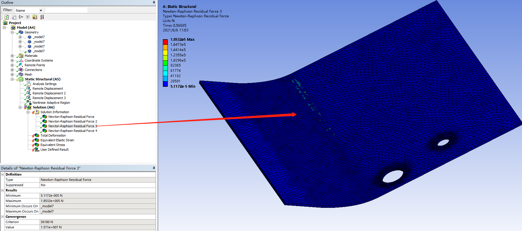
Please show the N-R Force Residual Plot.
Use File Archive and save a .wbpz file and attach that to your reply.
June 6, 2021 at 4:39 amSubscriberHello @peteroznewman
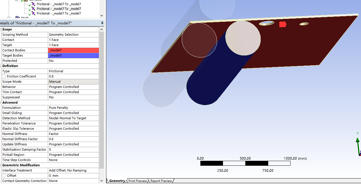
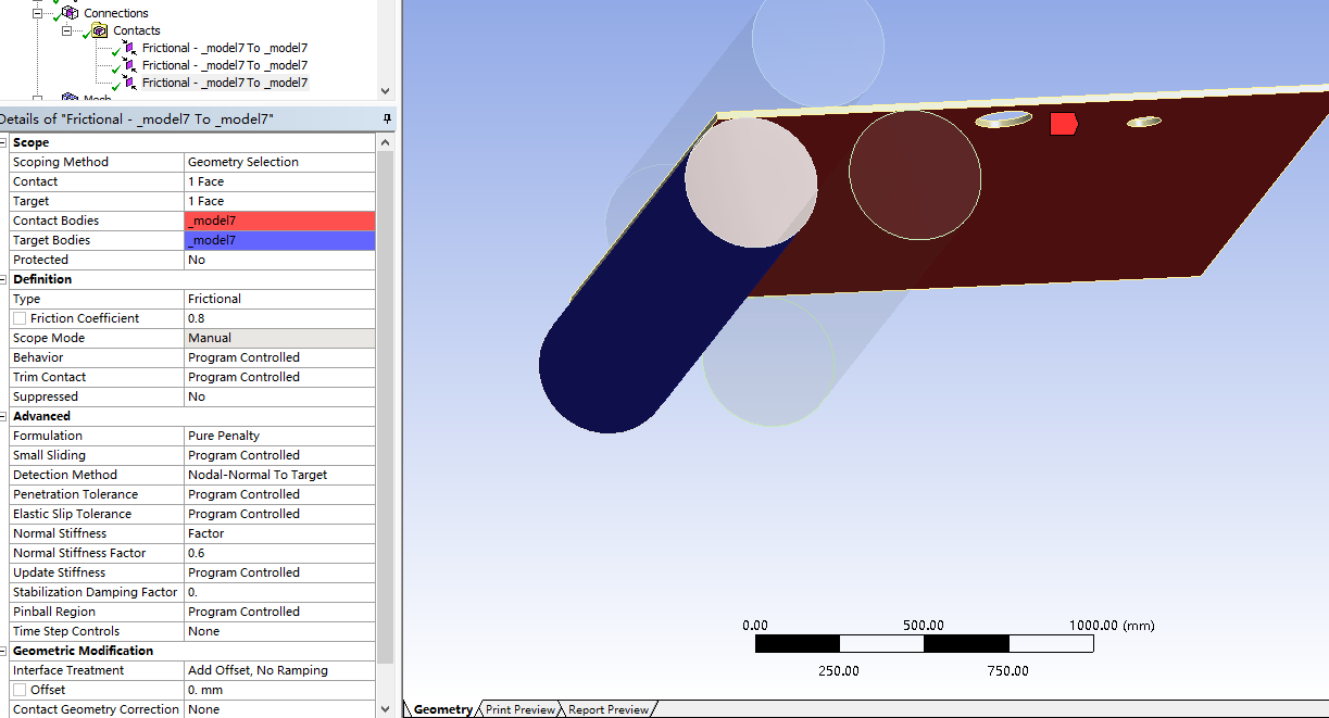
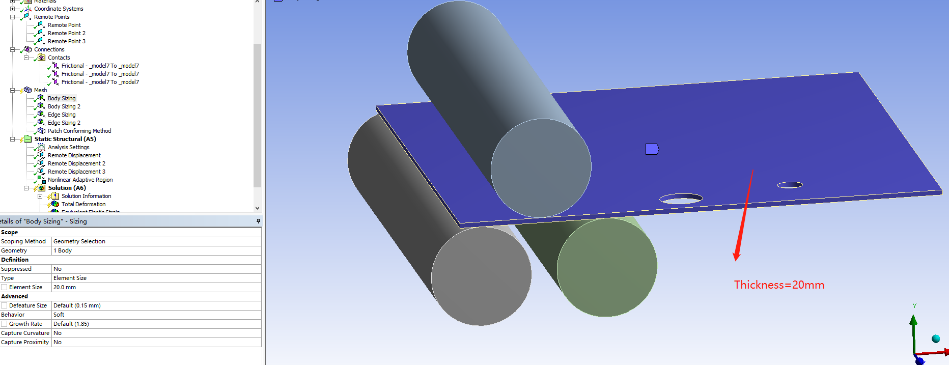
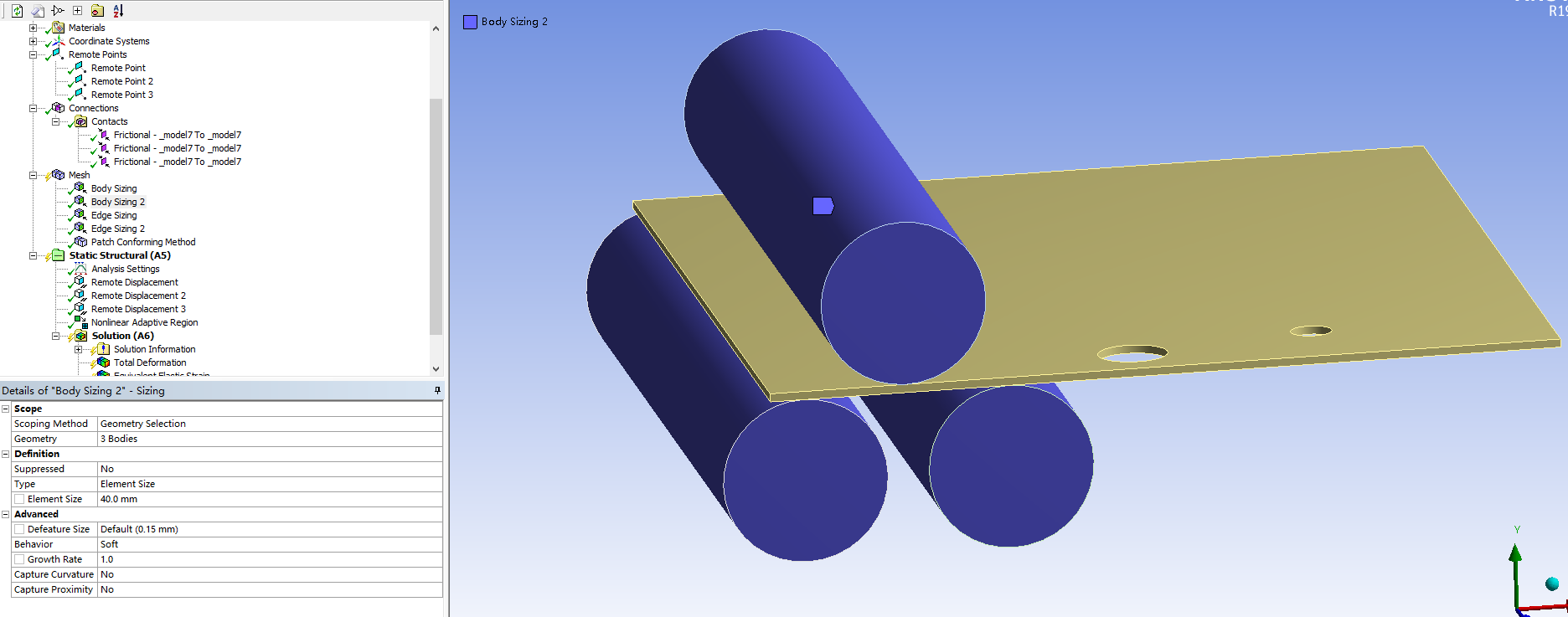
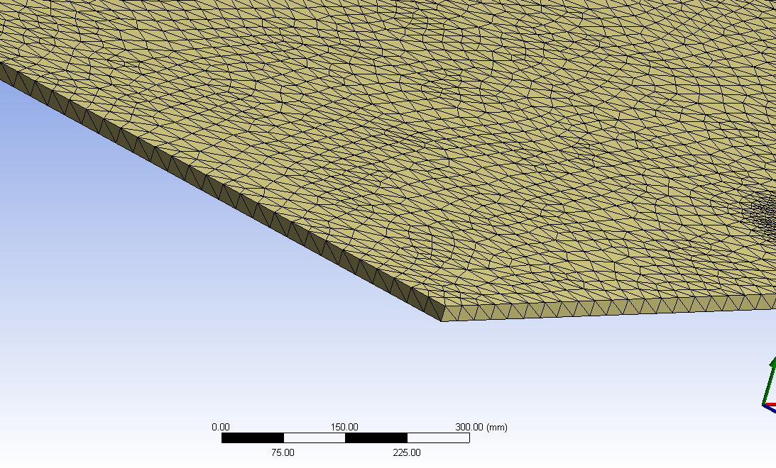
Thanks for your reply 1ÒÇüIn your last reply,You suggested me "Put 8 linear elements through the thickness of the sheet",I am sorry, I do not know how to do it ,just set the Element Size smaller? Here is the meshing image of the plate.
2ÒÇüI simulated this process by ANSYS WORKBENCH19.2.
3ÒÇü
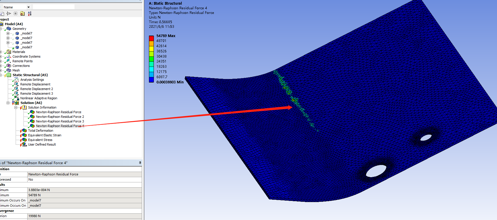
 4ÒÇü
4ÒÇü
I saved a .wbpz file but it is too big to attach.
June 6, 2021 at 5:30 pmSubscriberHello Qing Apply a Mesh Method called Sweep. The source face is one side of the thickness. The Sweep Elements can be set to number of divisions.
If you Clear Generated Data on the Mesh in Workbench, then do File, Save, then do File, Archive, the archive file size will be reduced.
June 7, 2021 at 7:12 amChinmay
Subscriber
I am not an expert but going through you post I observed few points I would like to share which I learnt during initial experimental stages of Static Structural. (maybe you are familiar with most of them)
1) In Bi-linear hardening, I could not see value of tangent modulus you used but in general do not use tangent modulus of 0 MPA (perfectly plastic) which contributed in convergence issues in my case.
2) In case of high plastic strain, I usually go for 2D plain strain model as suggested by Peter (maybe try mid surface in Space Claim but make sure plane is XY and no thickness in Z-axis). This will give an idea about what you are thinking is in line with what the software understands, if it works, you can go for 3D models.
3) The metal sheet you have used is quite long for initial try, because the longer it is, the more number of nodes and elements it will have and more time it will take to solve the problem.
4) In mesh settings, right click on Mesh --> show --> Sweepable bodies, you must see that the sheet is sweepable or you might have made some mistake in above steps, add Method, select sweep then manually select contact and target faces. (I see you have used NLAD, which cannot have that mesh). Then select no of elements to 6 (in case of NLAD) or 8 otherwise.
5) The friction coefficient value is quite high for metal to metal contact is what I believe which is another possible cause for convergence issues (if it is high, try reducing it till you get some results, then maybe try to increase a bit in next tries)
6) For initial tries, try not changing advance analysis settings, program controlled are best to try (otherwise you wouldn't understand where exactly you made mistake) Like pure penalty with normal stiffness value of 0.6 and in static analysis define by "steps" instead of "time". In initial substeps I think 100, minimum substeps 100 and maximum 10000 would be fine.
7) In NLAD, the remeshing takes place around 0.35 is what I can see in Force convergence graph, so try setting NLAD as manual if possible (but then # of steps needs to be increased, maybe try this later in simulation to improve results)
8) If you want finer mesh for specific part sheet (initially), use body split (divide the sheet into 2 or more bodies) in SC at appropriate distance and give different meshing to them reducing number of nodes and elements.
9) Save as this project to other name, clear results and meshing but keep all settings you need like remote displacement etc and then try to Archive this project to .wbpz extention for smaller archive file size.
10) Right click on solution information, insert, deformation and strain plotter will help you understand problems earlier than when the problem fails completely. (Select both trackers, right click and switch them to automatic update)
If I made some mistakes in this comment, Peter will definitely teach us something new.
Thanks CK
Viewing 9 reply threads- The topic ‘How to choose the correct simulation module’ is closed to new replies.
Innovation Space Trending discussions
 Top Contributors
-
peteroznewman
 6304
6304 -
scabo
 1906
1906 -
Dennis Chen
 1457
1457 -
javat33489
 1308
1308 -
Shyam Prasad V Atri
1022
Top Rated Tags
© 2026 Copyright ANSYS, Inc. All rights reserved.
Ansys does not support the usage of unauthorized Ansys software. Please visit www.ansys.com to obtain an official distribution.
-
Ansys Assistant will be unavailable on the Learning Forum starting January 30. An upgraded version is coming soon. We apologize for any inconvenience and appreciate your patience. Stay tuned for updates.