
TAGGED: mesh-generation, solid185
-
-
July 14, 2021 at 8:56 pm
MickMack
SubscriberHi Guys,
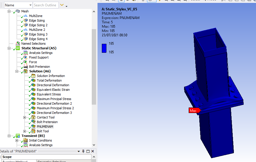
I am trying to replicate a study from the literature by Styles et al (2016) whereby i must create a simulation of a connection namely the vertical tie as shown below. I could use some assistance in assigning the SOLID to be used.
July 15, 2021 at 6:17 am1shan
Ansys EmployeeIn addition to changing the element order to linear you also need to add a command snippet under the respective geometry object - 'et, matid, 185'. Also, these are 2 useful videos you might want to check - https://www.youtube.com/watch?v=UzFh_UbUF4k and https://www.youtube.com/watch?v=gRUeyWTwJ2g.
Regards Ishan.
July 15, 2021 at 9:03 amSubscriber
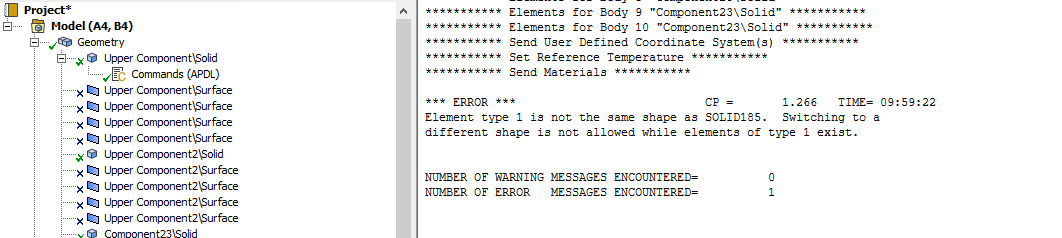
I have inserted this command under the geometry object and i keep getting the same error, as shown below regarding "switching to a different shape is not allowed". I have tried a number of different variations including adding KEYOPT2(3), and changing the mesh from linear to quadratic.
I also inserted the command separately into pre-processing but it made no difference.
Could you offer any further advice?
Many Thanks Michael
July 15, 2021 at 11:22 amAnsys EmployeeSolid 185 is a hexahedral element and the mesh probably contains some tetrahedral elements which is causing the error. Use mesh controls to create a pure hex mesh on the part to which the snippet is added.
Regards Ishan.
July 15, 2021 at 7:56 pmSubscriber
I have been able to create the solid185 without the use of the command snippet. However i have tried to insert a command snippet under the geometry to change KEYOPT 2(2), which appears to be the default to KEYOPT 2(3).
Could you advise how to do this i have tried a variety of different commands but keep getting errors as shown below, stating 0 is not a valid id number.
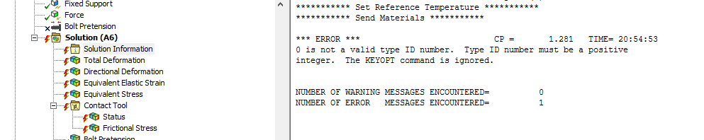
Regards Michael
Details of creating 185 solid
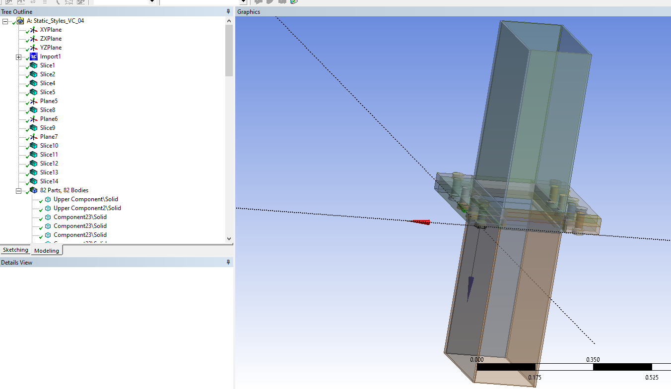
To create the hexahedral mesh necessary as indicated in a previous post i had to slice the solids in the design modeller to create simpler solid with sweepable bodies. I followed the process shown in this video https://www.youtube.com/watch?v=oOAx4j3D2rc, shown in the first pic below. Once this was done i returned to mechanical and automatically generated my mesh ensuring that the element order selected was 'linear'. Once i sent the model to the solver solid 185 was automatically assigned to all solids as shown in the last picture below.
July 21, 2021 at 7:46 amSubscriber
Could you assist me with changing the KEYOPT as described above.
Thanks Michael
July 22, 2021 at 7:09 pmSubscriberHi guys Can anyone offer sum advice on how to change KEYOPT2 as detailed above.
Any advice much appreciated
Thanks
July 22, 2021 at 11:17 pmpeteroznewman
SubscriberThe default element order is quadratic, not linear. Therefore the elements that were used were probably SOLID186 and not SOLID185. SOLID186 are quadratic elements and there is no Keyopt(2)=3 defined for this element.
Go to the Mesh Details window and set the Element Order to Linear instead of Program Controlled. Then you will get SOLID185 elements and the command object will work.
July 23, 2021 at 7:31 amSubscriber
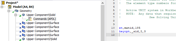
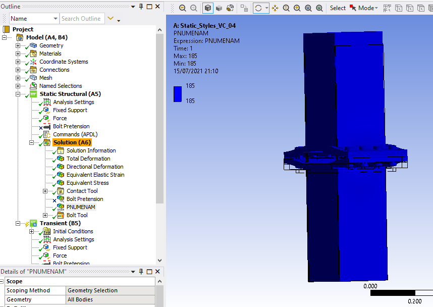
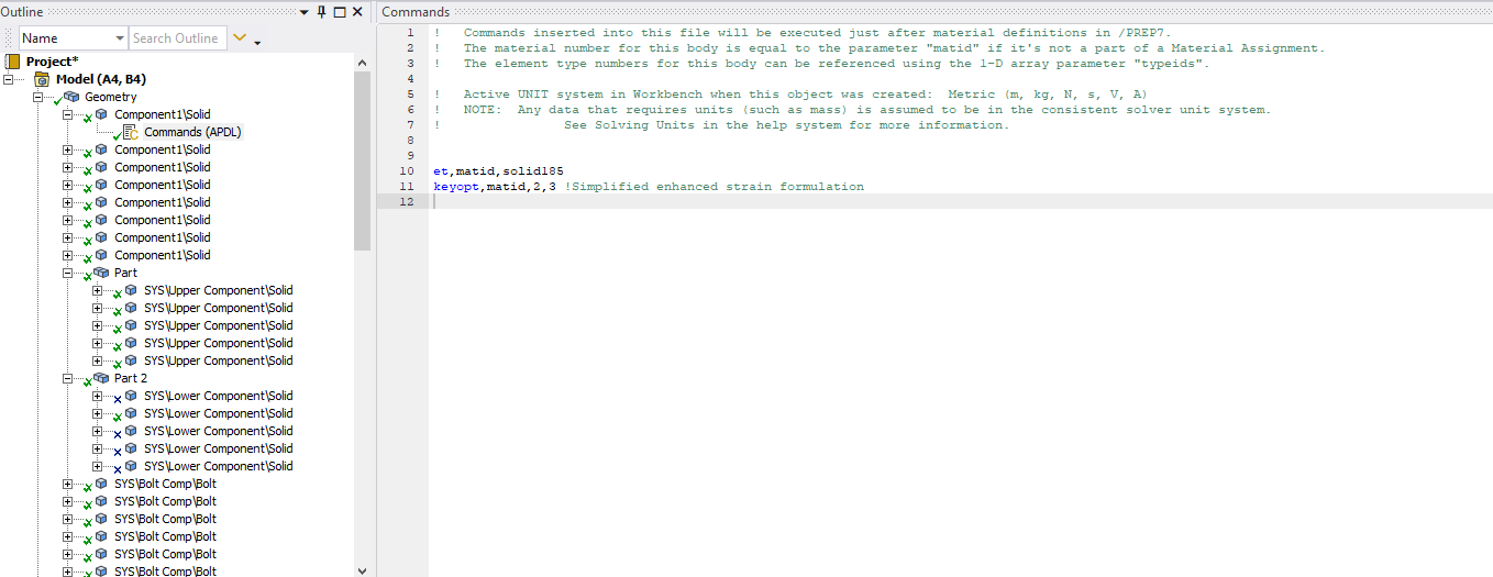
I have already changed the mesh element order to 'linear' and i have checked that the solids are SOLID185, please see both snippets below.
Can i take it that the command snippet below is correct.
et,matid,185
keyopt,_sid,2,3
If so should the snippet be inserted into the tree with the boundary conditions, or do i need to add it to each solid in the geometry tree?
Thanks Michael
July 23, 2021 at 8:05 amEmperor
Subscriber
you have to add the extract to each solid in the geometry tree. If you want to use the keyopt on the same element, you must also put matid and not _sid (as far as I know) i.e. :
Et,matid,solid185
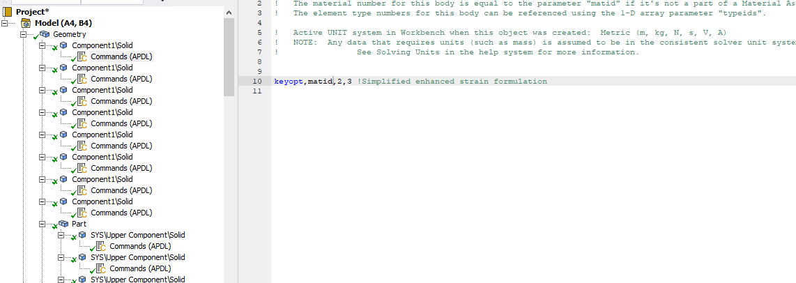
keyopt,matid,2,3 ! Simplified enhanced strain formulation
You can then check in the output of the solver that the solid185 has been used with the right keyopt, just do a Ctrl+F and search for "solid185".
July 23, 2021 at 6:42 pmSubscriber
Thanks for the reply
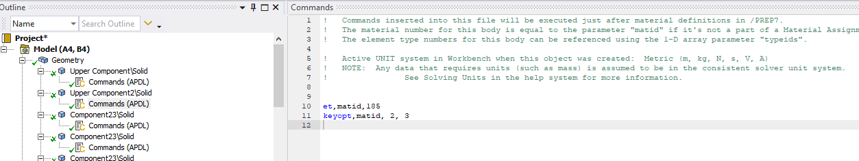
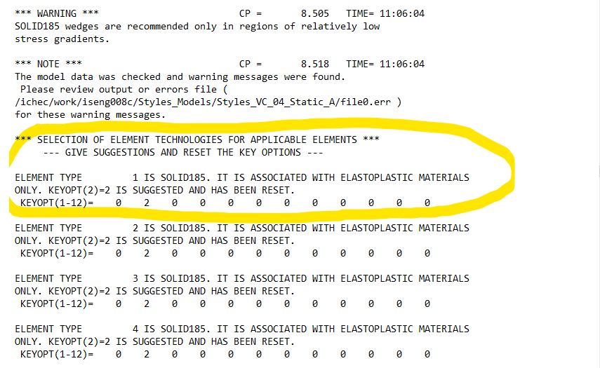
I have added that command to all the solids within my geometry, but it still does not appear to have worked. As you can see the solver is still assigning KEYOPT2(2). 2 images shown below.
I don't see the command snippet in the solver output so i don't believe it is reading it at all. I would expect to see *****Begin Command Snippet* **** in the output file.
I'd appreciate any further suggestions on how to remedy this.
Thanks Michael
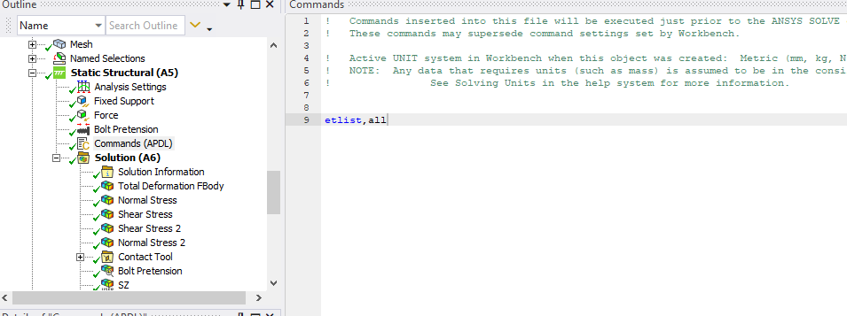
July 23, 2021 at 9:41 pmSubscriberyou have to set the Element Control to Manual to stop the solver from overwriting your Keyopts.
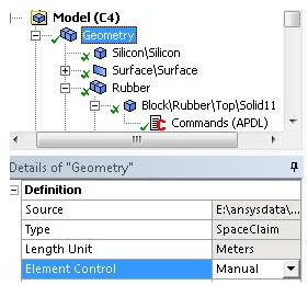 Under the body you want to apply the control, you insert a command object and type
keyopt,matid,2,3
You don't need the first line because the elements are already type 185.
Regards Peter
August 14, 2021 at 7:35 amSubscriber
I did what you suggested but i am sorry to say that it is still not working. I have included the images below. I am applying it to all solids in the model.
Michael
August 14, 2021 at 12:18 pmSubscriberWhat do you mean it's not working?
Before the solver said keyop(2)=2 is suggested and has been reset.
Now it just says keyop(2)=2 is suggested but does not say it has been reset.
August 14, 2021 at 12:42 pmSubscriberApologies i did not register that difference,does that mean it is working?
Is there a way to check what keyopts are being used in an analysis? Usually there is a line of zeros beneath the respective keyopts, or a number under it as shown in the previous image.
Thank you for reverting back
August 14, 2021 at 12:53 pmSubscriberYes, it should show the line of zeros and there will be a 3 in column 2 of the line of zeros.
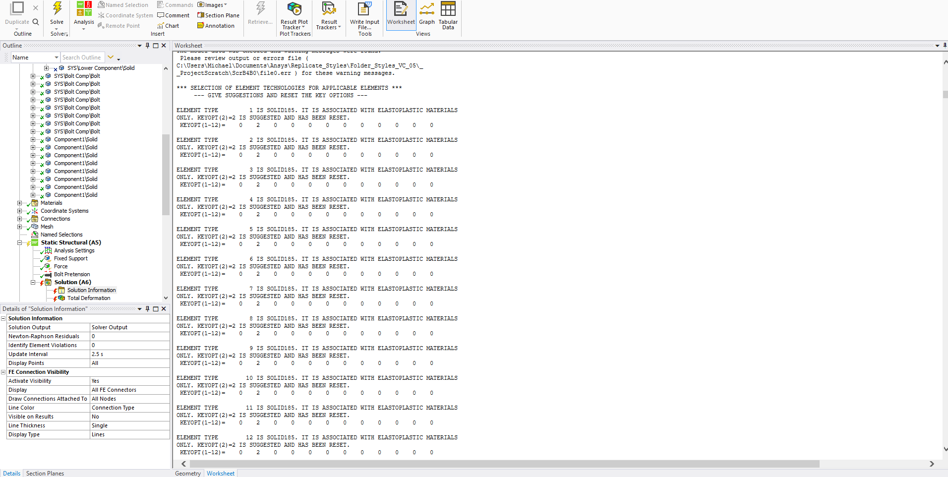
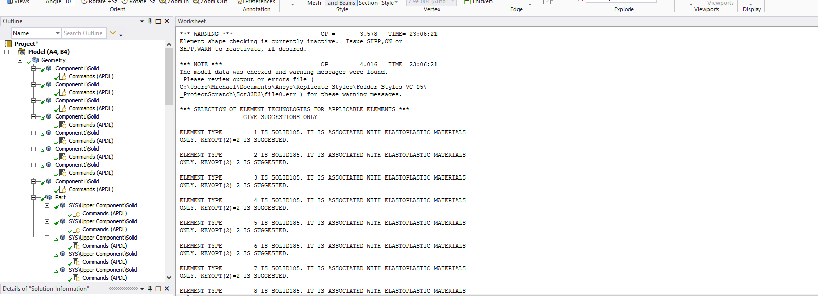
August 17, 2021 at 10:12 amSubscriber
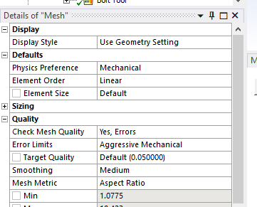
I have tested two scenarios both with the element control setting set to 'Manual'. The first on the left in the image below includes the keyopt command (keyopt,matid,2,3 !Simplified enhanced strain formulation) on all the solids, excluding the bolts. The second scenario does not include this command snippet. As shown in the image below both scenarios will "Give Suggestions Only", and i cannot tell what keyopt is active as the customary line of zeros is not shown anywhere in the output file, it seems to only be shown when the setting is "GIVE SUGGESTIONS AND RESET THE KEY OPTIONS",as highlighted in the last image.
I have also been unable to locate the snippet command in the output file, i assume it should be visible in the document.
At the moment i cannot tell if the inclusion of the command is changing the keyopt correctly, as the results appear to be the same even when the command is not included.
Thanks.
Michael
August 18, 2021 at 10:05 pmSubscriber
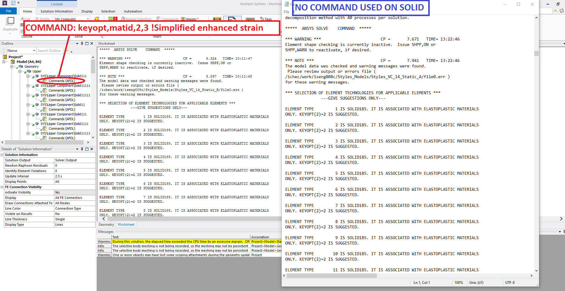
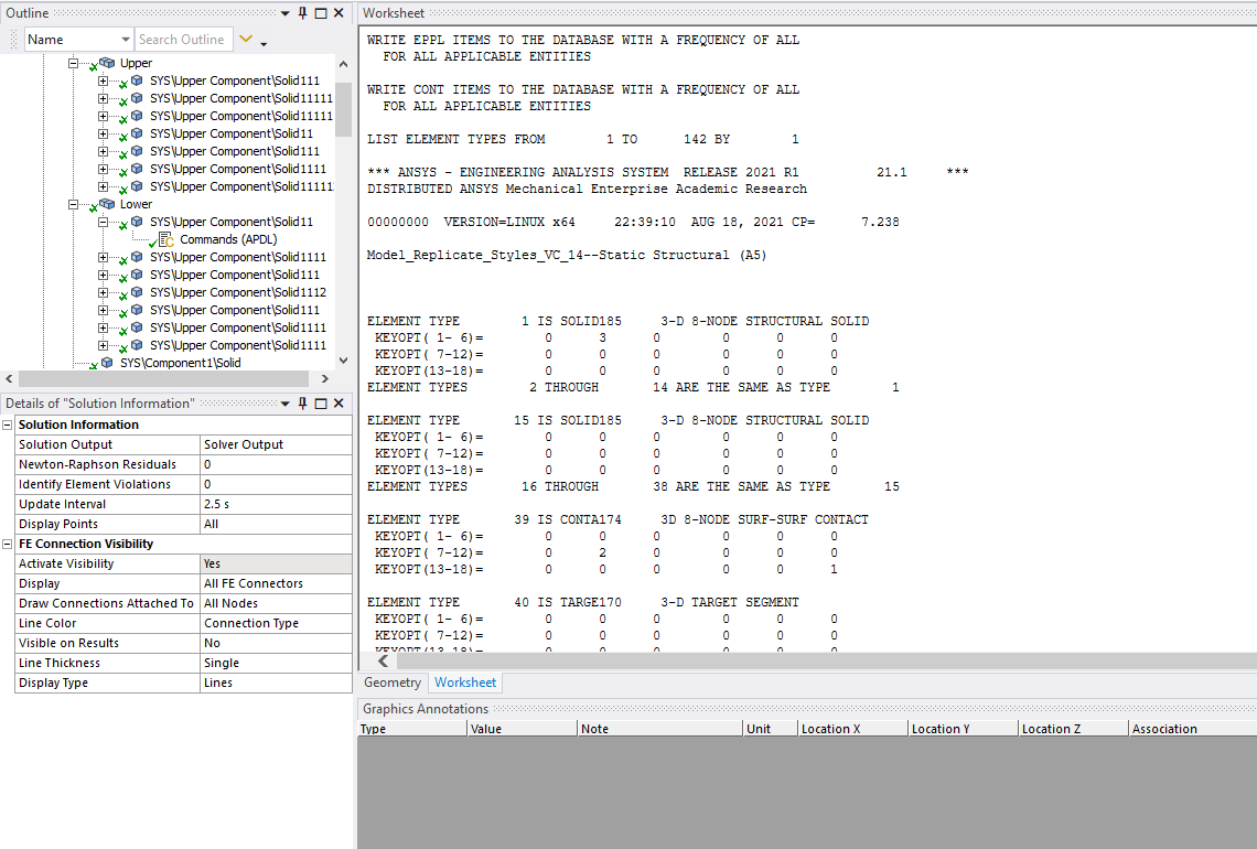
I have been able to confirm that the keyopts are working correctly by using the command ETLIST,all. In the solution information all the keyopts are visible shown in the last image below.
Thank you again for your generous assistance.
Regards Michael
Viewing 17 reply threads- The topic ‘How to change a SOLID187 into a SOLID185?’ is closed to new replies.
Innovation Space Trending discussions
 Top Contributors
-
peteroznewman
 6625
6625 -
scabo
 1906
1906 -
Dennis Chen
 1469
1469 -
javat33489
 1311
1311 -
Shyam Prasad V Atri
1022
Top Rated Tags
© 2026 Copyright ANSYS, Inc. All rights reserved.
Ansys does not support the usage of unauthorized Ansys software. Please visit www.ansys.com to obtain an official distribution.
-


The Ansys Learning Forum is a public forum. You are prohibited from providing (i) information that is confidential to You, your employer, or any third party, (ii) Personal Data or individually identifiable health information, (iii) any information that is U.S. Government Classified, Controlled Unclassified Information, International Traffic in Arms Regulators (ITAR) or Export Administration Regulators (EAR) controlled or otherwise have been determined by the United States Government or by a foreign government to require protection against unauthorized disclosure for reasons of national security, or (iv) topics or information restricted by the People's Republic of China data protection and privacy laws.
