

-
-
January 7, 2022 at 5:22 pm
xyjxyj1992
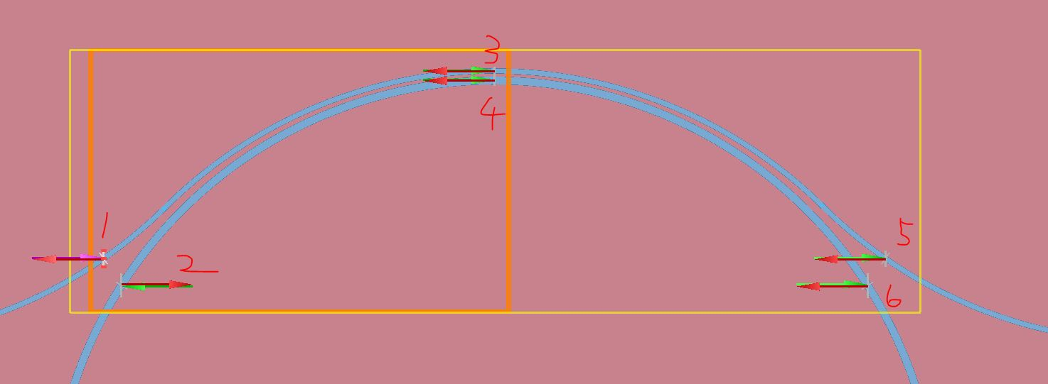
SubscriberHi, I want to calculate the transmission characteristics (transmission of the through/drop port) of the coupler shown in the attached figure by calculating only half of the coupler structure since the coupler is symmetric with respect to the x = 0 axis. Is it possible to deduct the transmission characteristics of port 5 and 6 by the S parameters of port 1-4? Thank you!
January 7, 2022 at 7:09 pmGuilin Sun
Ansys EmployeeI believe this is a more theoretical question other than simulation.
Sure you can simulate half the device, since it is symmetric. If at the ports there is only one fundamental mode, things can be much easier: from ports 1,2 to ports 3,4, you get the s parameters, and it is lossy, so you only need to double the loss will give you the transmission at ports 5 and 6. You could use transfer matrix or scattering matrix to get the exact results, since you know the s parameters at each port. You will need to flip signs for the second part. The details are up to you to develop. More modes would also work if you use more s parameters.
You could use the "s parameter utility" to get more helpful info: S-parameter matrix sweep utility
Ring resonator getting started - Final parameter extraction
Ring resonator getting started - Design and initial simulation
I think you will need to spend more time than the simulation to develop a math model for this.
January 17, 2022 at 5:58 pmSubscriberThank you so much for your reply! I guess I am still a little bit confused about the parameters that can be extracted from the port expansion tab. For example, if I were to calculate the transmission of one specific mode of port 4 with the excitation only at port1, would that be T_in or T_out from port expansion of port 4? Or would that be abs(S)^2 of from port expansion of port 4?
January 18, 2022 at 1:11 amAnsys EmployeePlease refer this https://support.lumerical.com/hc/en-us/articles/360034902433-Using-and-understanding-Mode-Expansion-Monitors
abs(S)^2 is originated from S parameters.
But I am not sure where T_in and T_out are from. The regular port gives
 Please get more information on mode expansion result here https://support.lumerical.com/hc/en-us/articles/360034902433-Using-and-understanding-Mode-Expansion-Monitors
and a Chinese post Ansys Insight: Õà│õ║Ämode expansionþøæÞºåÕÖ¿þÜäõ¢┐þö¿ÕÆîþ╗ôµ×£Õêåµ×É
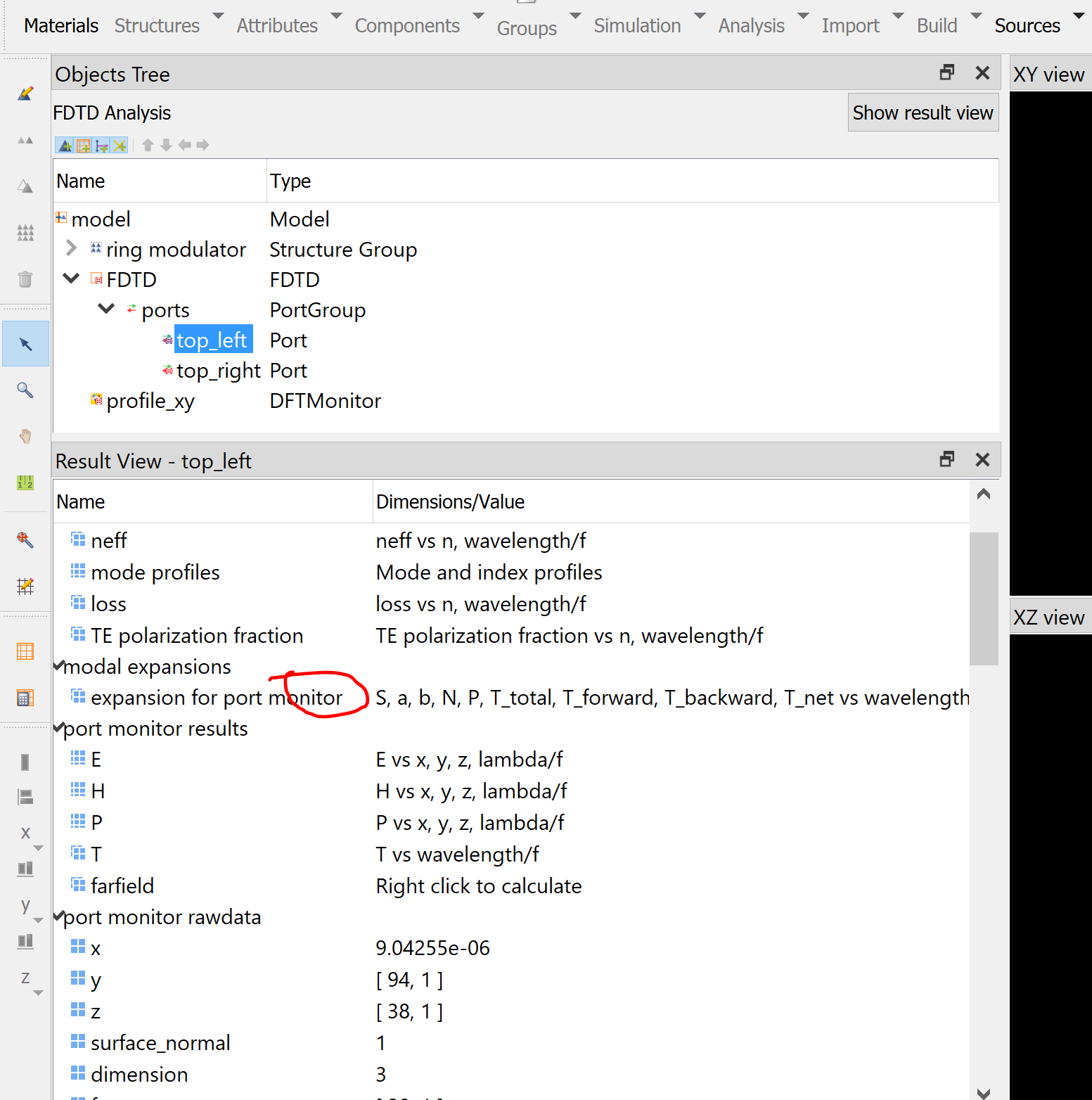
January 18, 2022 at 1:33 amSubscriberLike this one shows.
January 18, 2022 at 1:36 amSubscriberAnd what does S exactly stand for in this "modal expansions" tab. The website you provided does not include the information of S.
January 18, 2022 at 5:07 pmAnsys EmployeeI am sorry that I do not know which example you are referring for the T_in, T_out. We have used the above T_forward and T_backward for long time.
S parameter is used to describe mode amplitude reflection/transmission (field) coefficients. It is originally from microwave network analyzer. You can find some textbook to get some details. It is similar to Fresnel coefficients in traditional optics. Since this is fundamental concept, Lumerical does not provide any background.
January 18, 2022 at 5:18 pmSubscriber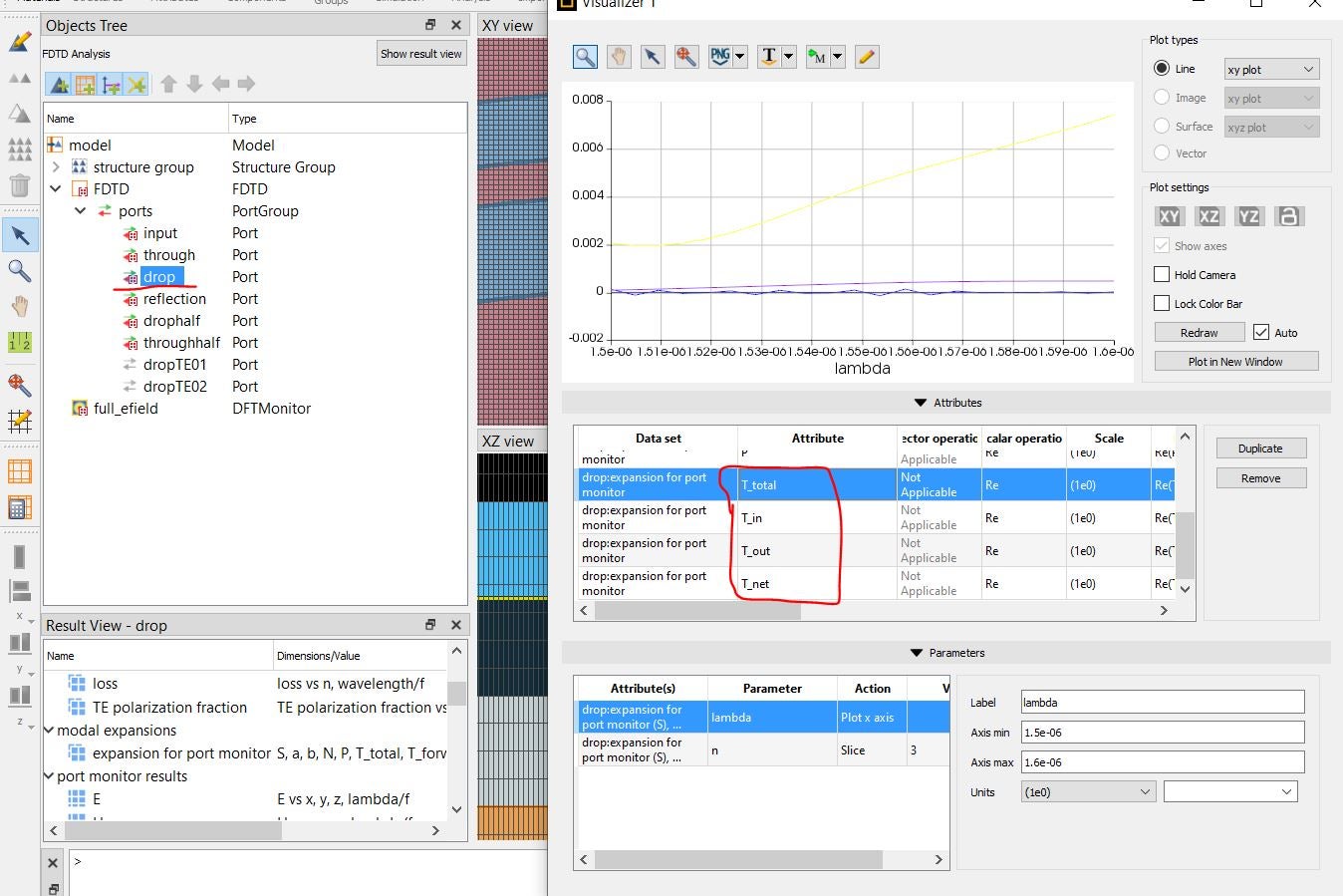 It is not only of the examples provided in your database, I was referring to the results I got from my own simulation file. Based on the definition of S parameters, abs(S41)^2 should give me the transmission of port 4 if there is only excitation from port 1 which should correspond or the exact same value of either T_forward or T_in in this figure. But these two do not match.
January 18, 2022 at 11:16 pmAnsys EmployeeOK, I got it. I took an online example https://support.lumerical.com/hc/en-us/articles/360042322794-Ring-Modulator
and got
 As you can see, they are similar. The difference if from their different calculation method.
As there is no documentation on T_in and T_out, I tend to believe they are the T_forward and T_backward.
I will file a feature request to correct this.
January 18, 2022 at 11:52 pmSubscriberThanks for the confirmation. I believe so too. Please correct me if I am wrong, if the injection direction of each port is forward. Should the transmission of top right be equivalent to T_in instead of T_out?
January 19, 2022 at 1:17 amAnsys Employeemost likely T_i is the T_forward, which means towards positive axis. You may infer this with their values, in and out can have significant difference. Each port will have T_in and T_out, which means T along positive and negative axis directions. Whether it is transmission or reflection will depend on the source injection. In addition, you may need to use your experience to deduct which quantity it refers. Port quantities are in general, it does not know the source injection is along positive axis or backward.
January 19, 2022 at 2:03 amSubscriberThat is what I believe as well. Injection direction is forward for all ports except for the port2. But results below with port 2 and 5 both indicate that abs(S)^2 matches well with T_out instead of T_in, even though I think T_in should be more reasonable based on my experience.

January 19, 2022 at 4:50 pmAnsys EmployeePlease ignore the difference of 1e-8. the bottom result shows you correctly to separate them.
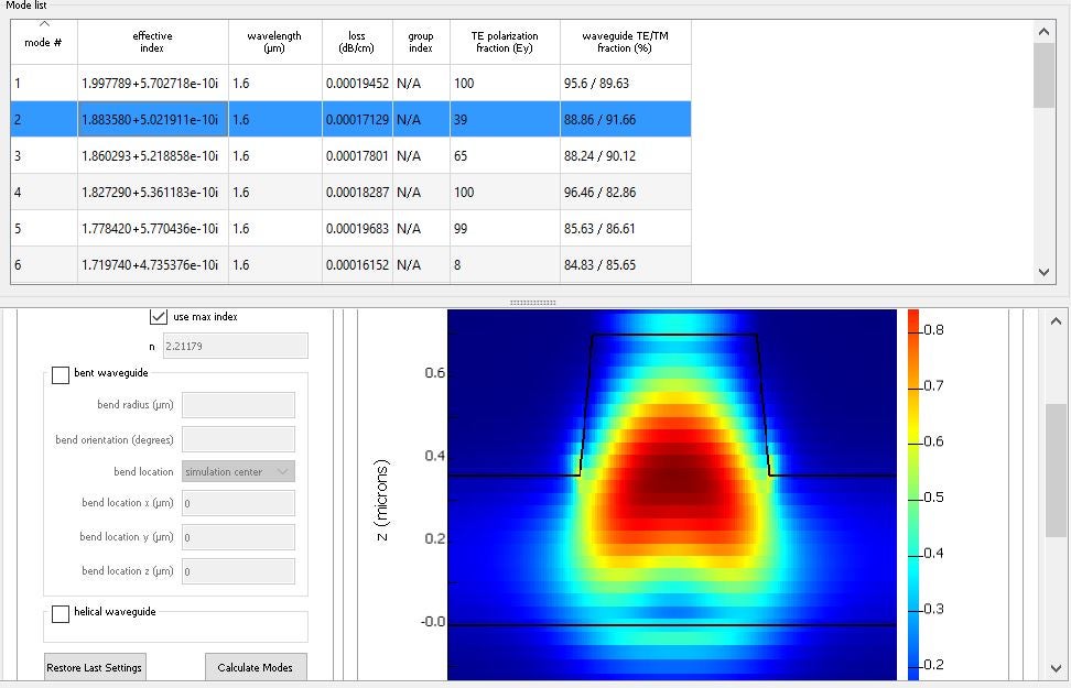
Not sure how to you excite the ports. But please use larger port size to capture the whole mode profiles. In particular port # 1,2 and 5,6. You can use a profile monitor to check what the fields look like at ports.
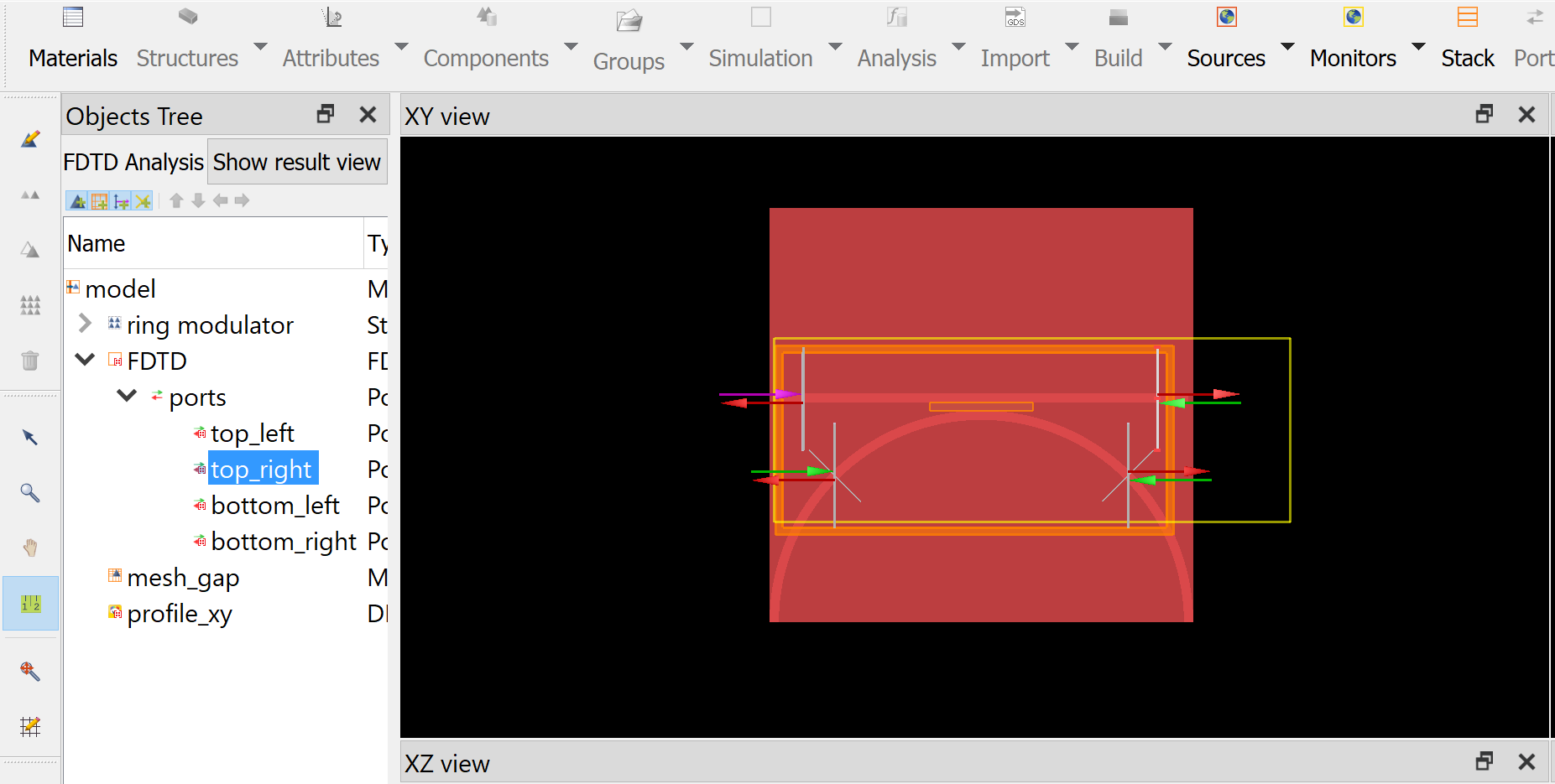
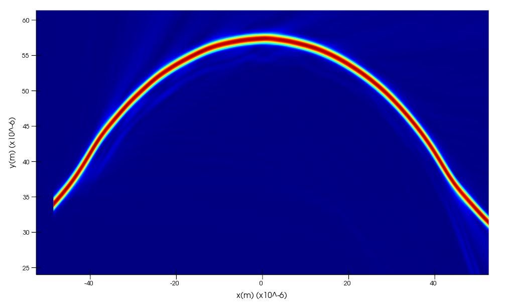
January 19, 2022 at 5:09 pmSubscriberThanks for your reply. I made sure the size of the port is wide enough and the mode profile is shown below:
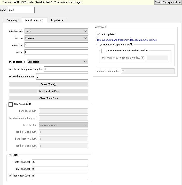
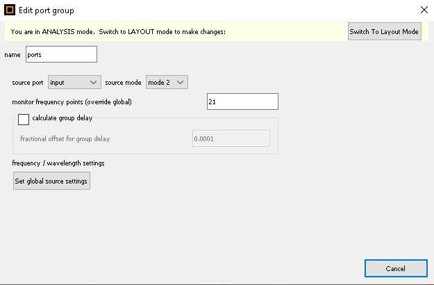
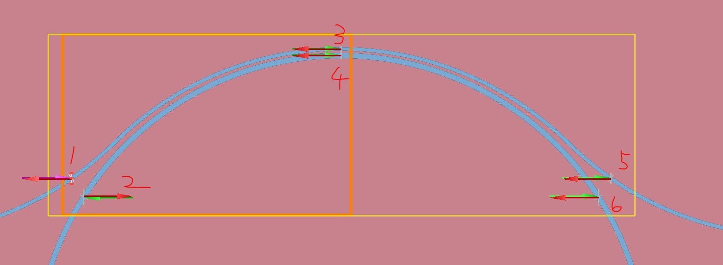
 The input port setup is shown here:
 Indeed, 1e-8 difference can be ignored. But that does not explain the results of port 5 above. T_out clearly matches with Abs(S)^2.
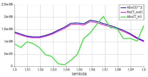
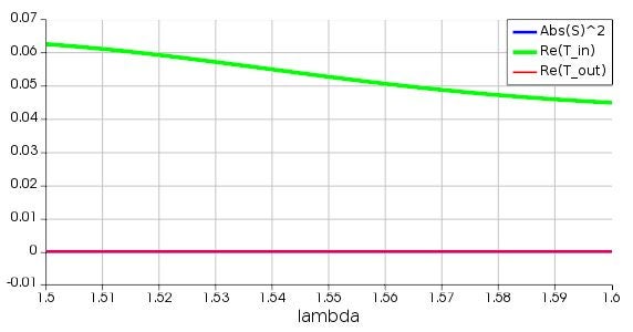
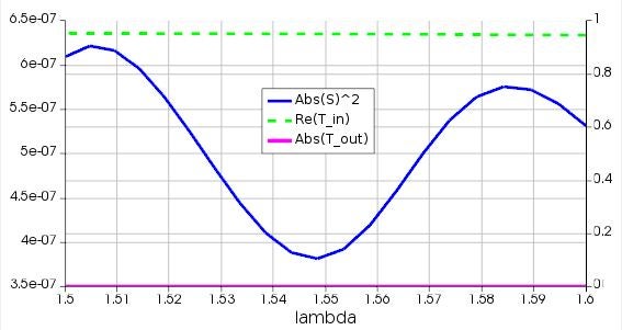
January 21, 2022 at 4:20 pmSubscriberHi, I did another test yesterday. The results of abs(S)^2 and T_out are definitely not correct. As you can see from the E-field monitor, the majority of the power goes through port 5. However, abs(S)^2 and T_out of port 5 is basically zero (abs(S)^2 and T_out corresponds to y left axis while T_in corresponds to y right axis). Can you check and verify it with me since it is very important? Thank you!
January 21, 2022 at 11:32 pmAnsys EmployeeT_in and T_out may not well be defined. If T_out does not match abs(S)^2, please check T_in.
January 22, 2022 at 2:12 amSubscriberSorry about the confusion. As the results show, T_out matches with abs(S)^2 but they are not supposed to be the answer for the transmission of port 5. Since the E-field diagram clearly shows that the majority of the power goes through port 5, which means that transmission should very close to one and that matches with T_in. However, T_in does not match with abs(S)^2 at all.


January 24, 2022 at 5:21 pmAnsys EmployeeT_in and T_out do not have a definite definition right now. Currently only T_forward and T_backward are clearly defined. I would suggest that you use the variable that gives you correct result, disregard its "appearing" definition.
January 24, 2022 at 5:25 pmSubscriberI understand this. The purpose of verifying this is to, like I mentioned in the very beginning of this discussion, simplify the model by using scattering matrix. However, in the example I provided above, abs(S)^2 does not give the correct result that reflects the transmission of the port. Thus, it is invalid to be used for transmission calculation.
Viewing 18 reply threads- The topic ‘How to calculate the transmission characteristics of a coupler with symmetry’ is closed to new replies.
Innovation Space Trending discussions
 Top Contributors
-
peteroznewman
 5719
5719 -
scabo
 1906
1906 -
Dennis Chen
 1419
1419 -
javat33489
 1305
1305 -
Shyam Prasad V Atri
1021
Top Rated Tags
© 2026 Copyright ANSYS, Inc. All rights reserved.
Ansys does not support the usage of unauthorized Ansys software. Please visit www.ansys.com to obtain an official distribution.
-


The Ansys Learning Forum is a public forum. You are prohibited from providing (i) information that is confidential to You, your employer, or any third party, (ii) Personal Data or individually identifiable health information, (iii) any information that is U.S. Government Classified, Controlled Unclassified Information, International Traffic in Arms Regulators (ITAR) or Export Administration Regulators (EAR) controlled or otherwise have been determined by the United States Government or by a foreign government to require protection against unauthorized disclosure for reasons of national security, or (iv) topics or information restricted by the People's Republic of China data protection and privacy laws.
