TAGGED: photonics
-
-
January 10, 2023 at 4:51 pm
Loic Feukam Takoundjou
SubscriberI want to calculate the losses of a curved waveguide.
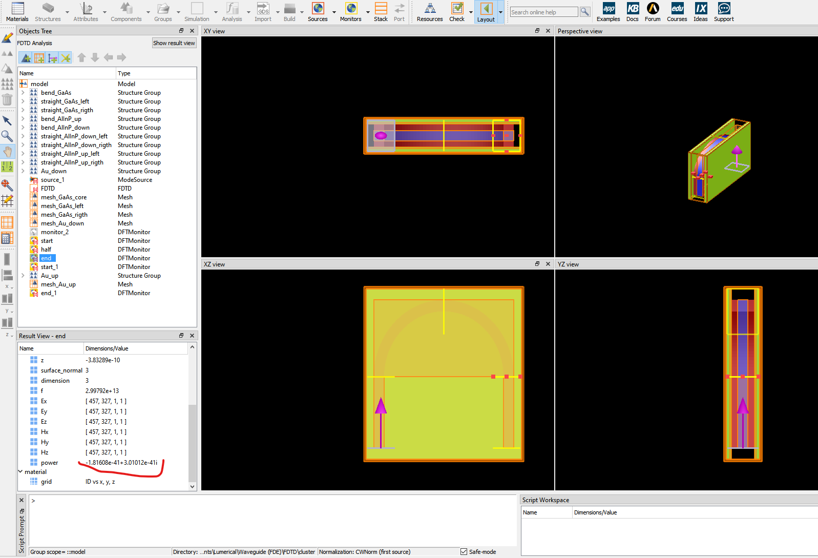
After defining the source, I have defined the monitors to give the transmission coefficient at different sections of the curved structure.
The power I get from the monitor placed at the end of the bend is negative and is of the order of e-41 and also has an imaginary part (see screenshot).
Is this a programming error?
How can I deduce the losses from the complex powers I get at the end?Thank you in advance.
-
January 11, 2023 at 6:57 pm
Guilin Sun
Ansys EmployeeSomehow my reply was not posted yesterday.
There are a few things:
1: negative power means the power flow is toward the negative axis.
2: the data you viewed is the raw power data without normalization.
3: Power is usually normalized to sourcepower transmission - Script command
4:For such bend waveguide, it is better to use FDE in MODE to get the loss contant:
Solving bent waveguides in FDE and FEEM
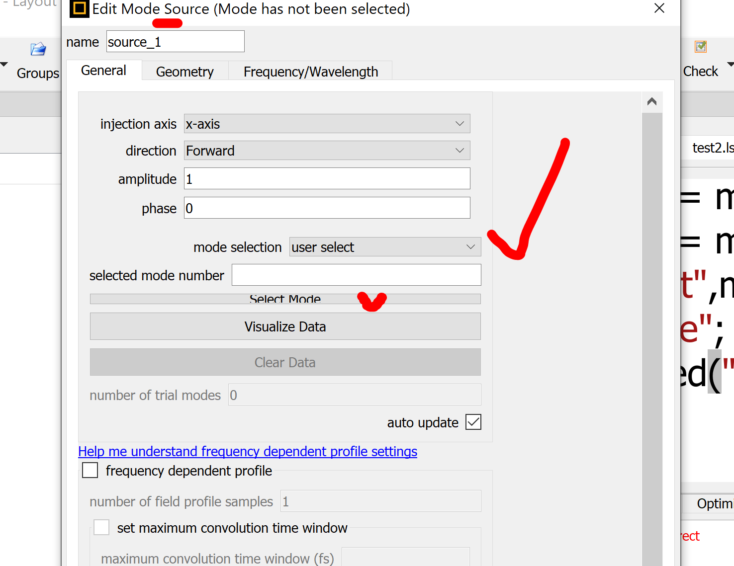
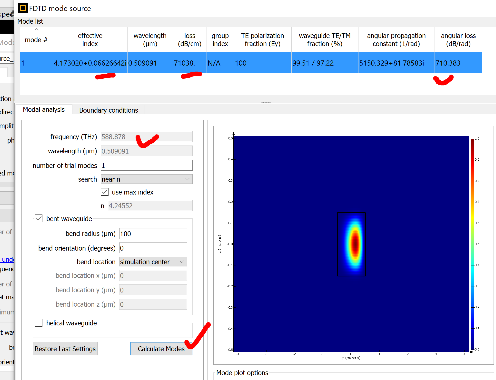
5: you can also use the mode source to get the bending loss: choose "user select" and calculate the mode
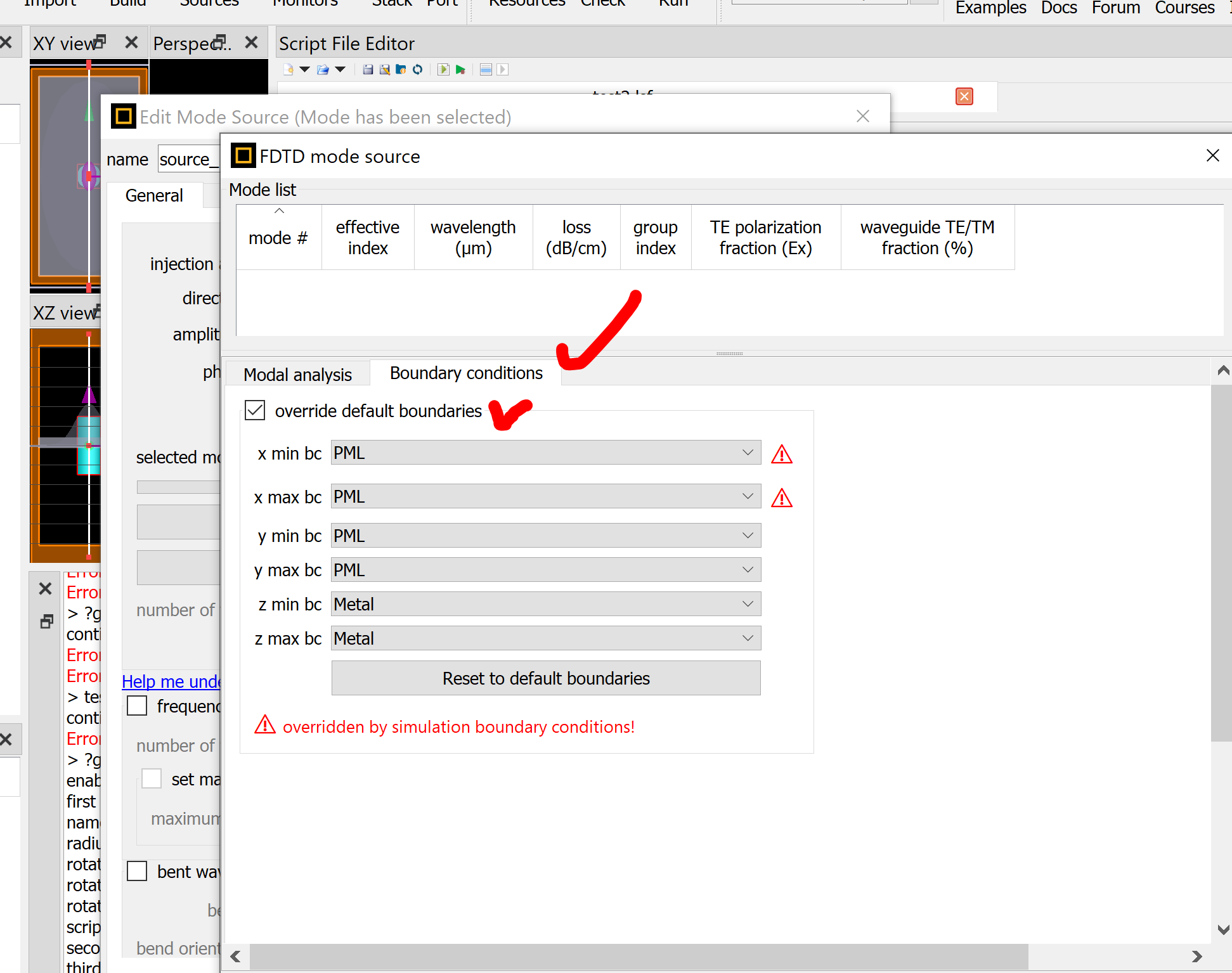
Choose PML boundary conditions:
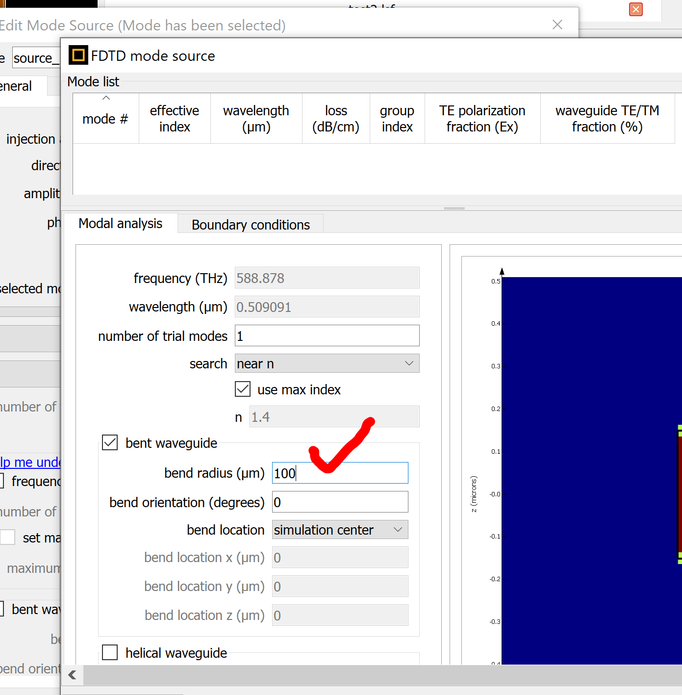
set the bending radius:
specify the wavelength or frequency, then "calculate modes":
Please try.
For the half circule bending, we do not recommend to simulate it using FDTD. If you really want, please use mode expansion monitor, or better port to get the modal S paramter.
Please write a new post if you have other questions.
-
January 17, 2023 at 9:19 am
Loic Feukam Takoundjou
SubscriberThank you for the informations, I have followed your instructions for calculating losses
-
-
October 21, 2023 at 9:39 am
Ahmad Murad
SubscriberI'm experiencing a similar issue, so I attempted to follow your instructions for calculating losses. However, I'm still encountering negative values for losses, specifically when analyzing different modes at varying radii. My design involves a bent waveguide, and I'm trying to create a graph that depicts the loss as a function of the bending radius. I would greatly appreciate it if you could explain in detail the steps to achieve this plot
-
October 22, 2023 at 10:04 pm
Guilin Sun
Ansys EmployeeSall negative values are due to numerical error. usually neff can be accurate up to 1e-5. Higher accuracy needs careful settings and testing.
Please write a new post as this post will not be monitored from today.
-
- The topic ‘how to calculate bending loss using 3D FDTD simulation’ is closed to new replies.


- Difference between answers in version 2024 and 2017 lumerical mode solution
- Errors Running Ring Modulator Example on Cluster
- Import material .txt file with script
- Trapezoidal ring
- Help for qINTERCONNECT
- Absorption cross-section of AuNR excited by prism-based TIR
- Issues with getting result from interconnent analysis script
- Topology Optimization Error
- How to measure transmission coefficients on a given plane .
- Edge Coupler EME Example Issue

-
1727
-
630
-
599
-
591
-
366

© 2025 Copyright ANSYS, Inc. All rights reserved.

