TAGGED: divergence, mechanical, rigid-elements, structural
-
-
November 2, 2021 at 6:08 pm
Rashi
SubscriberHello all,
I’m conducting transient simulation to see the effect of residual stress due to the solidification and cooling of an engine block.
The temperature profile is obtained using ANSYS Fluent.
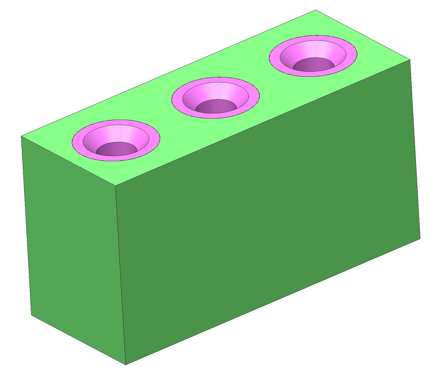
The following figure represents a simplified version of the geometry I’m using. The engine block is represented in green color and the cooling chills are represented in pink color.
November 2, 2021 at 7:49 pmpeteroznewman
SubscriberI'm not sure about the solidification step of the simulation.
For solid materials that are simply assembled at a uniform hot temperature and cooled to room temperature, a simple Static Structural model can compute the thermally induced stress. I recommend you use SpaceClaim to create Shared Topology to eliminate the need for Contact in the model. Assuming the four solid bodies are in a single part file, click on the Workbench tab then on the Share button. You will see all the common surfaces and edges light up. Click the green check mark to accept this. Now when you bring this file into a Static Structural model, the mesher will create a congruent mesh connecting all four bodies with no need for any contact.
Constraining a face to be Y=0 is already an over-constraint on the geometry. For example, you would not do that to a bimetalic strip, that would prevent it from curving as the temperature changed.
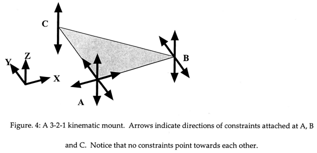
The correct constraint is called a Kinematic Mount, which allows for strain-free thermal expansion of a body of uniform CTE. Here is a recent post on that topic. /forum/discussion/comment/137006#Comment_137006
November 3, 2021 at 5:00 pmRashi
SubscriberThank you for your reply The reason for using transient simulation is to use the temperature data from Fluent. To see the effect of temperature gradient due to solidification at casting the engine block. I've checked static structural and still, the external thermal loads are a beta function therefore I did not use it.
Also the reason for having contacts is, I'm sharing the same model in fluent and mechanical and I need to specify automatic contacts which are used to define interface thermal conductivity in fluent and friction coefficient in mechanical.
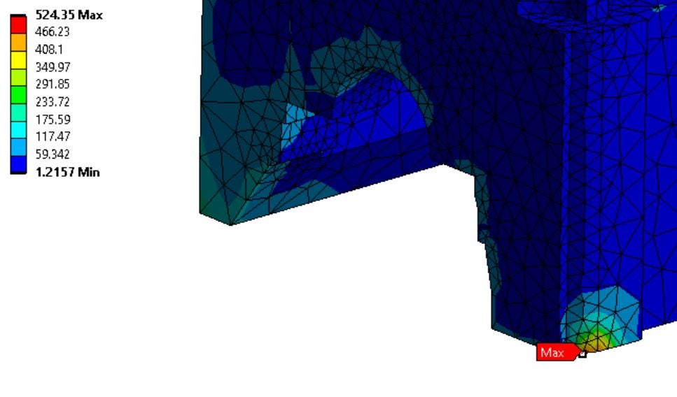
Thank you for the suggestion for the kinematic mount. However, even if we constrain 3 points with dx, dy and dy separately aren't we over constraining the geometry? I've tried to constrain engine block and the chills in three points with 3 DOF separately and at those points, I got highly localized stress concentrations.
The image below shows the localized stress created on a point in which I constrained one DOF.

November 3, 2021 at 8:58 pmpeteroznewman
SubscriberYou don't constrain X, Y and Z at each of the three points. Read carefully the description below.
From thisreference. Figure 4 shows a 3-2-1 kinematic mount. The three constraints at point A prevent translations in X, Y, and Z, but do not preclude rotations about A. The additional constraints at B prevent rotations about Z and Y, and the constraint at C prevents rotations about X.

If the mounted object were to change its dimensions, due to differential thermal contraction with the base, or small machining errors, for example, point A would remain fixed, and points B and C would move freely towards or away from A along their unconstrained directions. It is this allowed free motion which is the key to making a mount kinematic. If another constraint were added, for example an additional X direction constraint at B, then the distance between points A and B would be fixed, and a dimension change in the object would produce a stress.
November 7, 2021 at 12:33 amRashi
SubscriberThank you for the clarification it now makes sense now.
I've also managed to use static structural as you have mentioned. I found that I have been using other "external load" options.
Still, I'm having the issue of how to stop the chills from having rigid body motion.
I've tried introducing penetration in the first time step to keep the chills under pressure from the engine block.
Furthermore, I've tried adding a body-body connection between the bottom edge of the chill and the bottom edge of the cylinder bore.
I've only managed some luck when I used remote displacement on the chills to stop them from moving in the top direction. But the issue here is when I do so I get relative movement between the block and the chills in the top axis.
Cheers Rashi
November 8, 2021 at 7:56 amRashi
Subscriber
I found the reason why the chills are having rigid movement. Since the simulation starts from elevated temperature Ansys expands the geometry at the initial time step. This is not what I wanted, I want the engine block to contract with time. I found that this can be done by changing the reference temperature of the engine block and it worked.
Nevertheless, thank you for the suggestion on the kinematic mount technique!
PSA:
If anyone is doing a simulation on thermal contraction from elevated temperature remember to change the reference temperature of your geometry.
Use kinematic mount to mount the geometry to freely expand/contract the geometry.
Viewing 5 reply threads- The topic ‘How to avoid rigid motion for thermal stress simulaitons?’ is closed to new replies.
Ansys Innovation SpaceTrending discussionsTop Contributors-
3622
-
1303
-
1122
-
1068
-
1008
Top Rated Tags© 2025 Copyright ANSYS, Inc. All rights reserved.
Ansys does not support the usage of unauthorized Ansys software. Please visit www.ansys.com to obtain an official distribution.
-
The Ansys Learning Forum is a public forum. You are prohibited from providing (i) information that is confidential to You, your employer, or any third party, (ii) Personal Data or individually identifiable health information, (iii) any information that is U.S. Government Classified, Controlled Unclassified Information, International Traffic in Arms Regulators (ITAR) or Export Administration Regulators (EAR) controlled or otherwise have been determined by the United States Government or by a foreign government to require protection against unauthorized disclosure for reasons of national security, or (iv) topics or information restricted by the People's Republic of China data protection and privacy laws.


