TAGGED: ansys-apdl, current
-
-
October 19, 2023 at 8:04 am
zs
SubscriberSimulation platform: ANSYS Mechanical APDL
Dear all,
I tried to apply a current on one surface in the 3D model by command as below:
ALLSEL,ALL
VSEL,S,VOLU,,13
ASLV,S
ASEL,R,LOC,Z,8.33E-3
NSLA,S,1
CM,CURRNODE,NODE
CP,1,VOLT,ALL
*GET,TotalNodes,NODE,0,COUNT
F,ALL,AMPS,I/TotalNodesAs a result, the current was applied to the nodes along the X-direction, which was parallel to the surface. I wonder how to change the current direction to normal to the surface that is along the -z direction. I tried to modify the node coordinate by NMODIF and create another coordinate system with a different direction compared to the default Cartesian coordinate system. But they didn't work.
looking forward to your help.
-
October 19, 2023 at 3:57 pm
Bill Bulat
Ansys EmployeeHi Zhongchao,
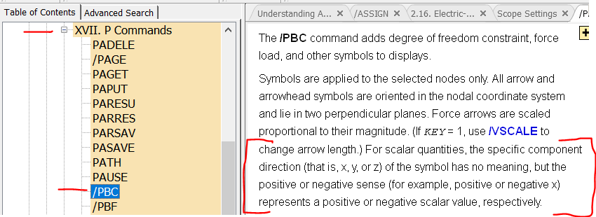
Actually, I'm quite certain your APDL code will apply the current in a direction normal to the surface at z=8.33E-3 (as you intend it to). My guess is that your concern stems from the appearance of the symbol representing your applied AMPS load (e.g., the image created by /PBC,AMPS,,1 followed by EPLOT). Current is a scalar, not a vector. In MAPDL, symbols representing applied scalar loads are always displayed pointing in the x direction. The /PBC documentation alludes to this, though the description is admittedly pretty vague:
Coupling the VOLT DOF on the surface as you have, the calculated voltage of all the nodes on that surface will have the same value => there will be no voltage gradient tangent to that surface => current will only be allowed to flow perpindicular to that surface.
One thing that may be a problem though (I'm not sure) is the last two lines of your code. After coupling VOLT, one typically applies all of the current to be applied at the surface to the single "master" (lowest numbered) node of the coupled degree of freedom set. I'm not sure applying current to the other non-master nodes (as you have done) will be recognized by MAPDL. You may end up having only I/TotalNodes current applied to the surface. The single command I would use in place of your last two commands is:
F,ndnext(0),AMPS,I ! APPLY ALL CURRENT ON THE NEXT HIGHEST NUMBERED NODE ABOVE ZERO
I'm confident that will work correctly.
Kind regards,
Bill
-
October 19, 2023 at 10:06 pm
zs
SubscriberDear Bill,
Thanks for your quick response and detailed reply. Yes, my confusion comes from the plot which shows the current in the X-direction and your answer is very helpful.
Btw, in the command you recommended at last, I didn't find the definition of ndnext(0) in the help document, could you please give me more information about this?
Thanks again for your help.
Best regards,
Zhongchao
-
- The topic ‘How to apply the current along the -z direction?’ is closed to new replies.


-
3407
-
1057
-
1051
-
896
-
882

© 2025 Copyright ANSYS, Inc. All rights reserved.


