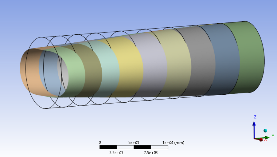
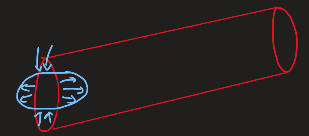
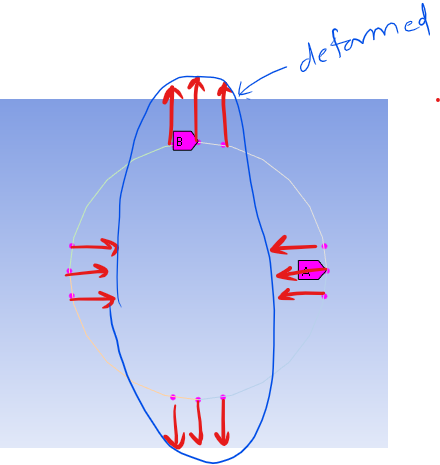
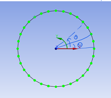
How to apply a radial displacement to the edge nodes of the cylinder?
TAGGED: cylindrical-coordinate, displacement, radial-force
-
-
February 20, 2025 at 1:50 pm
-
February 20, 2025 at 7:25 pm
Subodh Adake
Ansys EmployeeÂ
Â
Â
Hello,
This seems quite tricky.
Simple way: Select the nodes on the circle which lie close to horizontal and vertical axis and displace those in the required directions something like this:
This may not yield exactly the required shape but an approximate one.
Hard way:
Through APDL commands you can try the below steps:
- Get theta angles for all nodes on the edge with respect to cyclindrical csys placed at the center of the circle:

- Once this theta angle is known for each point you can find out ‘r’ for each theta using the ellipse equation in cylindrical co-ordinate system, using the below formula:

This will give you the final position (in cylindrical co-ordinates) that each node has to go to in order to make an ellipse. - Subtract the radius of the circle from the ‘r’ values calculated for ellipse at each theta angle. Finally this difference would be the radial displacement to be applied to each of those nodes. Displacement can be applied using the ‘d’ command.
Note: Make sure to use NROTATE command to align the nodal directions with the cylindrical co-ordinate system before applying the displacements.
- Get theta angles for all nodes on the edge with respect to cyclindrical csys placed at the center of the circle:
-
Viewing 1 reply thread
- You must be logged in to reply to this topic.
Innovation Space
Trending discussions
Top Contributors
-
6019
-
1906
-
1425
-
1308
-
1021
Top Rated Tags
© 2026 Copyright ANSYS, Inc. All rights reserved.
Ansys does not support the usage of unauthorized Ansys software. Please visit www.ansys.com to obtain an official distribution.


