Photonics

Photonics

Topics related to Lumerical and more.

How is free space treated in FDTD? Where to put monitors?

TAGGED: , ,

    • serenek4
      Subscriber

      Hello,

      My goal is to determine the reflection, transmission and absorption through a material. I have observed that when I have a FDTD simulation with a plane wave source illuminating a flat substrate from above and nothing else, the location of where I place my monitors matters greatly for my result. The monitor 10nm below the plane wave source has a higher amplitude vs the monitor 100nm below the plane wave source (both are above the substrate). Why is this? Shouldn't the amount of transmission through two monitors not change between monitor locations if there is nothing but free space in between them?

      Thanks!

    • Guilin Sun
      Ansys Employee
      When you say amplitude, do you mean the field amplitude or the reflection magnitude?
      I guess you have the following scenario :
      When you place a monitor in between the source and the top surface of the substrate, it records the interference fields, eg, the incident and the reflected fields. If you place the monitor above the source, you will have a uniform amplitude of E (and H). You can also place a line monitor along the propagation direction, you will see the interference , pure refection and transmission regions.
      I hope this helps. Please post your simulation settings if you still have questions.

    • serenek4
      Subscriber
      This makes sense for monitors located above the substrate. What about for monitors below the substrate? In my own simulation I extended the FDTD region below the substrate, and I placed several monitors beneath the substrate. My goal was to measure how much power transmission through the substrate. However, in this case the monitor's output also changed with respect to its z location (i.e. whether it was 10nm or 100nm below the substrate). Are there interference fields in this instance? Is there backreflection off the back surface? If so, where does that come from?
      Thanks for your help.
    • Guilin Sun
      Ansys Employee
      Could you please give some screenshots showing the structures and monitors?
      When we say substrate, usually we mean the substrate is extended outside of PML, as shown in my previous reply. However, from your description, it seems the "substrate" is inside the simulation region, which formulates a cavity. If monitor is inside the cavity, then your description is reasonable. Only when the monitors are located in uniform material without any material interface behind it, including air or background material, then the result should not change much in different locations. When there is aback surface, it will have reflection for sure.

    • serenek4
      Subscriber
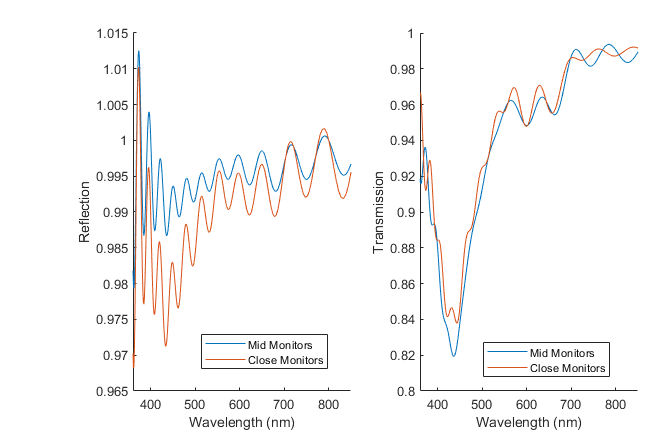
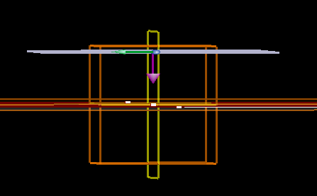
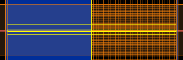
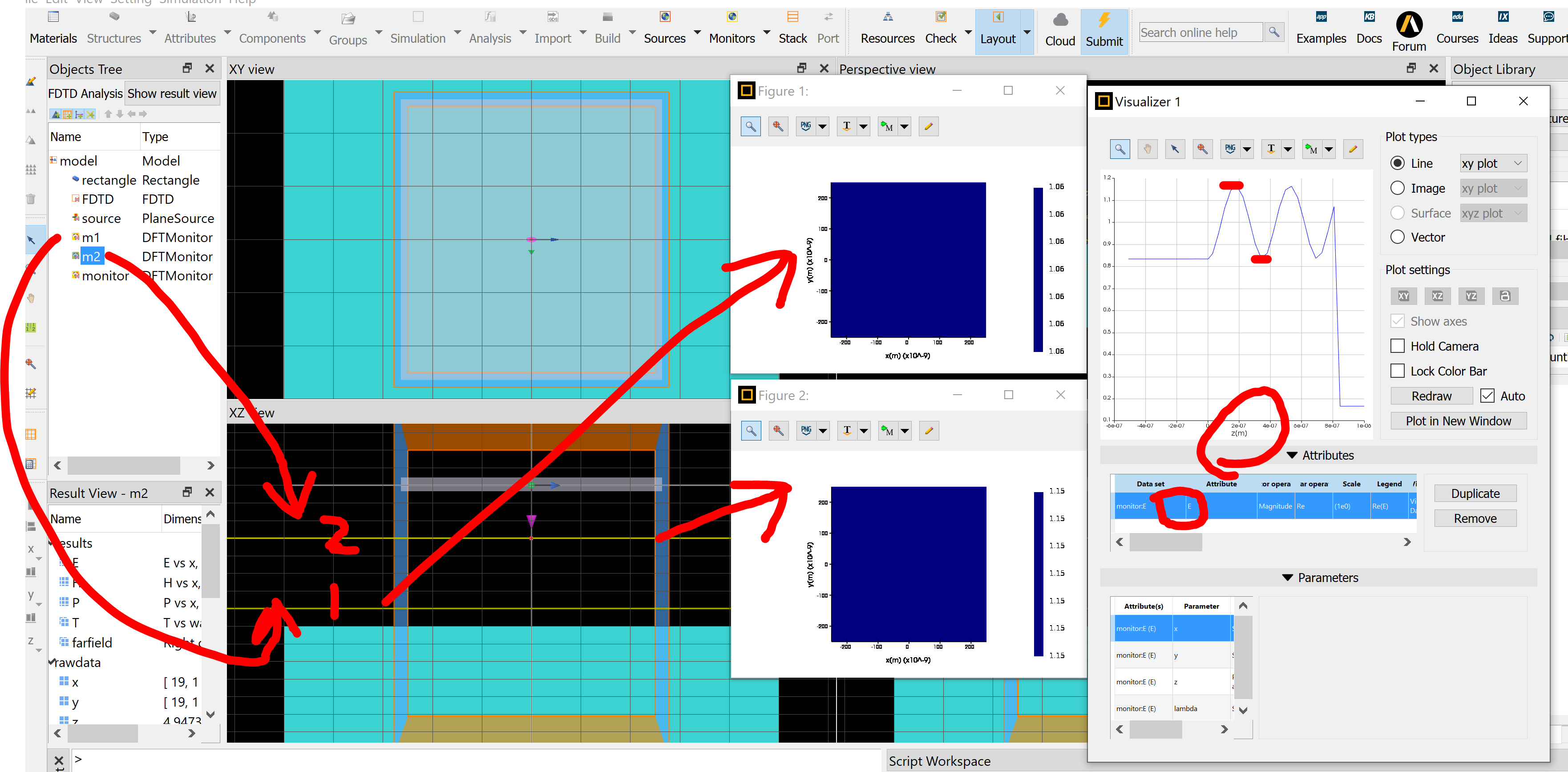
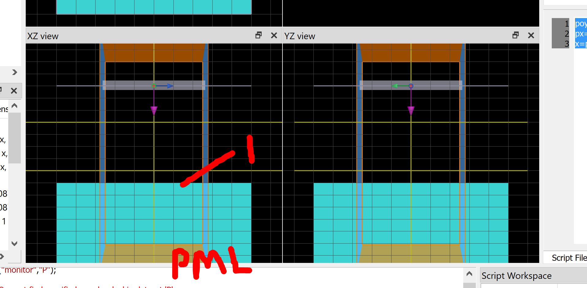
      The attached screenshots are below, which shows that I had a very thin flat material inside the cavity, with "close" monitors right next to the material and "mid" monitors farther from the material on both sides. I observed reflection from the black surface as you mentioned. Could you please explain what causes reflection / interference from the back surface? Also, in general, how would you recommend determining reflection AND transmission through a material? Specifically for reflection, would putting a monitor behind the source determine the material's reflection without interference from the incident wave?
      Also, I don't really understand what you mean by "Only when the monitors are located in uniform material without any material interface behind it, including air or background material, then the result should not change much in different locations." Isn't there always a material interface in the simulation as long as you have materials / structures? Could you provide an example of what you meant by this?
      Thanks for your help.


    • Guilin Sun
      Ansys Employee
      "Isn't there always a material interface in the simulation as long as you have materials / structures? Could you provide an example of what you meant by this?"
      not true. When the substrate is truncated by PML, except the top air/material interface, there is no other interface.

      Since it is a cavity, and you plot transmission and reflection, it is normal to have different peaks and valleys. PLease place a monitor behind the source and add R+T to check if it is smaller than or equal to 1 within simulation errors.

      When the monitor is in between the source and the front surface, you will need to add or substract 1 from the monitor transmission. Please refer this Tips for accurately measuring reflection in an FDTD simulation
    • Guilin Sun
      Ansys Employee

      For your simulation, there is another possibility: the simulation may need much smaller autoshutoff min than 1e-5. So please decrease it to 1e-8, increase simulation time, and check the monitor
    • schinta3
      Subscriber
      Hello
      I have an additional question for this. In this case, the slab of material has a finite thickness. If you extend the slab into the PML boundary to prevent the cavity reflections, how can you truncate the simulation to the slab's finite thickness? If the slab is extended, since the position of the monitor should give roughly the same power transmitted at any -z depth (assuming the slab extends into the -z direction through the PML. How would you get the transmission through a slab, especially a patterned slab, such as a photonic crystal?
    • Guilin Sun
      Ansys Employee
      "finite thickness" can mean things differently.
      1: if it is substrate, mm thick, you can simply use PML to truncate it, as its effects are only the Fresnel reflection at its far end with air (any device must be in air ultimately).
      2: if the substrate has um thickness, you can include it inside the simulation region. In this case, such substrate is suspended in air. It may require large memory and long simulation time.
      Yes you are right, that if the slab thickness is large and lossless, when you use PML to truncate it, the transmission should be the same, with very small numerical interpolation errors.
Viewing 8 reply threads
  • The topic ‘How is free space treated in FDTD? Where to put monitors?’ is closed to new replies.