
-
-
May 10, 2021 at 2:01 pm
oumaimalahmar.ol
SubscriberHello ,
Plz @peteroznewman
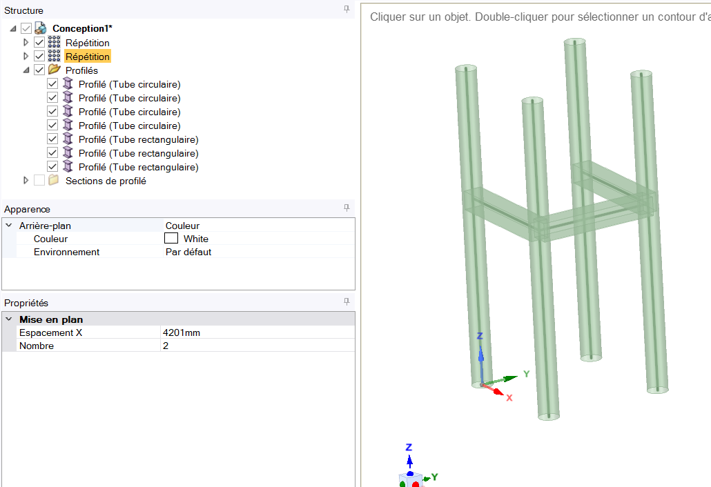
I wanted to draw a tank support on spaceclaim, with 2 profiles a circular tube and a square tube, I drew the support but it still in 1D how I can do to work in 3D in spaceclaim.
May 10, 2021 at 3:20 pmpeteroznewman
SubscriberBeam elements are a great way to quickly evaluate the tank support structure.
If you want more detail about the stress in the welded joints between the circular tube and the rectangular tube, then you need to go to the Design tab and extrude surfaces to represent the square profile and other surfaces to extrude a circle into a cylindrical tube. You will need to use Split Body to construct the intersection between the two tubes. Use the Prepare tab and click the Share button to create the weld line. When you bring those surfaces into Mechanical, you can mesh them, support the bottom edges and connect the top edges to the tank.
May 11, 2021 at 7:02 amSubscriberI don't know how I will create the surfaces.
May 11, 2021 at 7:30 amErKo
Ansys EmployeeIf you do not want beam elements, then sketch the cross section as a sketch and then use the pull tool to extrude to a 3D body representing that member (column or beam).
All the best
Erik
May 11, 2021 at 9:15 amSubscriber
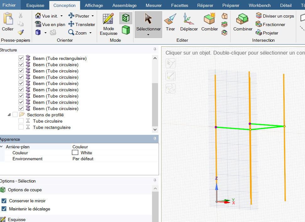
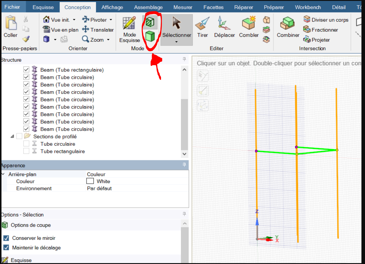
When i click on the 3D mode in design, it changes nothing it still beams
May 11, 2021 at 10:35 amAnsys EmployeeHi
OK, I think we need to explain more what we mean.
See this video on how you should create 3D representation of your parts.
So start a new model, and do like in the video and as shown for the first 25 seconds in the video. 1. So define the cross section (sketch), which in the video is a square section (you would need to sketch your section, say tube or I, whatever it is), and then finally extrude it (sketch of section) into a 3D part.
When you have all members defined as Peter said you will need to use Split Body to construct the intersection between the two tubes. Use the Prepare tab and click the Share button to create the weld line.
May 11, 2021 at 11:45 amSubscriber
I know how to do it but it's not the same for my case, here I draw lines after I import the profiles I wanted, and from these profiles I can't make a surface extraction.
In the normal case we do PULL but in my case it already draws the profiles and my structure remains in 1D.
May 11, 2021 at 12:14 pmAnsys EmployeeHi
Just to close this from my side - follow the video to do what you need.
Finally, have in mind you can not extrude a beam cross section (what you call profiles-'profiles I wanted, and from these profiles I can't make a surface extraction': you can not extrude these, these are only for assigning sections to beam element), you need to have a sketch as in the video, so you need to define those yourself manually in SC from scratch, and then which you can then finally extrude like in the video.
That is it really.
All the best
May 11, 2021 at 12:19 pmSubscriberhow i can define the sketch manually, can you help me plz Thank you
May 11, 2021 at 12:45 pmAnsys Employee
First, I would step back and recommend to take a course in the use of SpaceClaim:
The above course is a good start before proceeding with the part mentioned here next.
Once you are confident with the basics in SC, try this part.
So start a new model, and do like in the video and as shown for the first 25 seconds in the video. 1. So define the cross section (sketch), which in the video is a square section (you would need to sketch your section, say tube or I, whatever it is), and then finally extrude it (sketch of section) into a 3D part.
When you have all members defined as Peter said you will need to use Split Body to construct the intersection between the two tubes. Use the Prepare tab and click the Share button to create the weld line.

May 11, 2021 at 1:04 pmSubscriberthank you so much so what you advise me is not to use beams directly but to draw the profiles.
normally in solidworks there is a way to draw the beams and work in 3D I don't know why here on spaceclaim there isn't one.
the problem is that I work on the same geometry one in 3D and the other I did in spaceclaim in 1D but I find different results
May 11, 2021 at 1:49 pmAnsys EmployeePLease see information/training about beam modelling and solid modelling (we have courses on that) in Ansys.
So for frame type of structure, we can either use beam elements just like you did initially and you showed in your first post and what one would recommend to do here (if we care about the members themselves and not their connection details or any other 3D details that are not captured by a beam elements) , or we can use 3D parts which you show above and which should not be really used here since you will get a lot of strange stress results (due to corners).
Since we are going off topic here, please create a new post if you have any other questions, and other members in the forum might be able to help also.
All the best of luck.
Erik
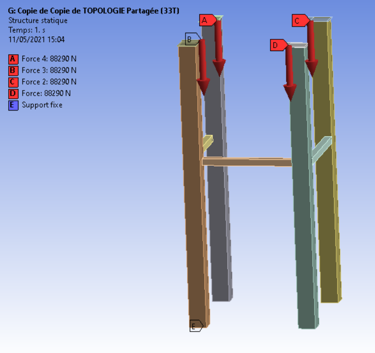
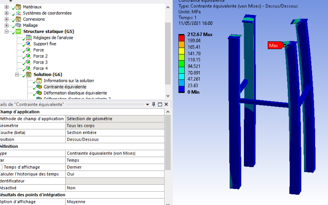
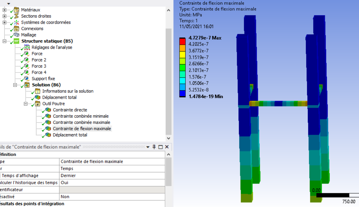
May 11, 2021 at 2:04 pmSubscriberThank you Indeed, with the 3d model I find a max stress of 212 MPa and in the corners on the other hand in 1D I find a stress of 4.07 e-7 MPa?
I have no idea where this difference in stress level comes from and why we have a foreign stress in the 3D module?
even the location of the constraints is different
Viewing 12 reply threads- The topic ‘how I draw the 3D profiles on spaceclaim’ is closed to new replies.
Innovation Space Trending discussions
 Top Contributors
-
peteroznewman
 6044
6044 -
scabo
 1906
1906 -
Dennis Chen
 1431
1431 -
javat33489
 1308
1308 -
Shyam Prasad V Atri
1021
Top Rated Tags
© 2026 Copyright ANSYS, Inc. All rights reserved.
Ansys does not support the usage of unauthorized Ansys software. Please visit www.ansys.com to obtain an official distribution.
-


The Ansys Learning Forum is a public forum. You are prohibited from providing (i) information that is confidential to You, your employer, or any third party, (ii) Personal Data or individually identifiable health information, (iii) any information that is U.S. Government Classified, Controlled Unclassified Information, International Traffic in Arms Regulators (ITAR) or Export Administration Regulators (EAR) controlled or otherwise have been determined by the United States Government or by a foreign government to require protection against unauthorized disclosure for reasons of national security, or (iv) topics or information restricted by the People's Republic of China data protection and privacy laws.
