General Mechanical

General Mechanical

Topics related to Mechanical Enterprise, Motion, Additive Print and more.

How do I get deformed geometry

    • mingyao.ding
      Ansys Employee

      I would like to get the shape/geometry of the result of a structural simulation I ran.

    • peteroznewman
      Subscriber

      There are two approaches to get the deformed geometry out of a Static Structural solution into a CAD program: a two step process and a fifteen step process. Thanks to SimuTech group for teaching me this method.


      FOR VIEWING OUTSIDE FACES ONLY


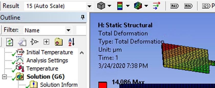
      In Mechanical: Insert a total displacement for a selected body into the solution, then right click on it and export an stl file.  


      In CAD:  import the stl file. Some CAD systems don't handle imported stl files very well. New versions are getting better at that. See the next approach.


      TO CREATE A SOLID BODY (more useful in CAD programs)


      Here are the steps to export a Parasolid file:


      In Mechanical:


      1. Create a Named Selection named "top" that contains the part you want to export.

      2. Analysis Settings set to Save APDL db
        def1
         

      3. Drop a Mechanical APDL component onto the Static Structural Solution 
        def2

      4. Right click on Analysis row of Mechanical APDL system on project page and select "Add Input File" 

      5. Select attached input file upgeom.inp (this is setup to select a single part in your model).

      6. Drop an FE Modeler component onto the Mechanical APDL Analysis

      7. Update the Static structural solution, Mechanical APDL Analysis, and FE modeler. 
        If the Static structural solution was done before step 1 above, clear generated data first.


      Open FE Modeler


      8. Right click on "Geometry Synthesis" and select "Insert>>Initial Geometry"


      9. Right click on "Initial Geometry" and select "convert to parasolid"


      10. Drop a DesignModeler (Geometry) Component onto FE modeler Model cell


      11. Update FE modeler and DM


      Start DM (double click on Geometry field)


      1. Add a  Body Operation, "Type" set to Sew, setting the "Create Solids?" to Yes


      If the result is not a single solid, change "Tolerance" to User Defined.


      def3


      13. In DM open Tools>>Options then go to:


      DesignModeler>>Geometry>>Export Options>>Parasolid Export Version and select 24.0 for NX8


      14. Export Parasolid file. 


      15. In CAD system import Parasolid file.

    • peteroznewman
      Subscriber

      This site won't allow a file with an inp extension to be attached, so below is the contents of upgeom.inp which is attached as upgeom.txt


      resume


      /prep7


      cmsel,s,top


      esln,r


      upgeom,1.0,1,last,file,rst


      cdwrite,db


      finish

    • peteroznewman
      Subscriber

      Does AIM have a method to get the deformed geometry back to SpaceClaim?

    • CakeOrDeath
      Subscriber

      Hi,


      Great walkthrough! However, I seem to experience a problem when converting to a parasolid. Even though my initial geometry turns out OK, all faces, vertices, etc are detected correctly, when I convert to parasolid it doesn't detect any of the geometry correctly. I'm just trying the process out with a deformed beam so I wouldn't have thought it was too complicated to handle.


      Any advice?

    • peteroznewman
      Subscriber

      Please attach your workbench archive .wpbz file and let's take a look. Also say what version of ANSYS you are using.


      You would think ANSYS would build-in a useful output in a simple way, such as right mouse click > Export Deformed Geometry.

    • CakeOrDeath
      Subscriber

      Hi,


      Thanks very much! Hopefully I have created the .wpbz file correctly, but if there are any issues then please let me know.


      I'm using ANSYS version 17.1.


       Indeed! Clearly there is a need for people to use the deformed geometries in CAD software or for further analysis in other software packages, so you think it would an easier process.


    • peteroznewman
      Subscriber

      Hi,


      By carefully following the directions, I was able to get a deformed Parasolid in the end, but I had to try twice. The first time I didn't get good surfaces so I went back and changed the Mechanical Units to mm then it worked.


      Attached is an ANSYS 17.1 archive.

    • CakeOrDeath
      Subscriber

      Hi,


      Thank you so much for all your help! I changed the units and that seemed to fix everything.


      I knew it would be some setting that I didn't have quite right that was holding me back


    • earvinlloyd
      Subscriber

      Hi,


      Now that FE-modeler is phased out (in 19.1 and newer), what is the substituting procedure (besides exporting to .stl)?

    • Rob
      Forum Moderator

      It's been relabelled as "External Model", so try that. 

    • lordofthethings
      Subscriber

      Both External Model and Mechanical Model are not attaching with Mechanical APDL.

    • NRafael
      Subscriber

      Hello,


      I've been trying the procedure to obtain the solid model. But I am not understanding the step 5. Where I am supposed to get that input file?


    • peteroznewman
      Subscriber

      This post has the text for the input file. Just rename it with a .inp file extension.

    • lincs2k9
      Subscriber

      As "FE modeller" is not available in Ansys latest version, this thread's procedure is not applicable for latest version ansys workbench. "External Model and Mechanical Model" are not working according to this procedure. Can you provide instruction using latest version? Is it possible? 

    • mehdimechanic
      Subscriber

      Can this single part in step 5 be an assembled part? some parts together? then how should the input be modified? 

    • lordofthethings
      Subscriber

      For newer versions of Ansys that do not have a "Finite Element Modeler"


      1. Run the simulation to get deformed geometry :


      2. Connect the solution part of the static structural to a new instance of "Mechanical Model", update the tolerance if necessary, and check the following options in the properties of the Mechanical Model. Update both the systems.


      3. Finally, bring a new instance of the "Geometry" system and connect the model to it. 


      4. Open the Geometry module in DM (Not Spaceclaim), generate it, and then File --> Export --> (STEP format). Wait until the conversion is over. Now you have the solid model ready!


    • Rob
      Forum Moderator

      Have you also linked Engineering Data? 


      Edit: don't need that, and it works fine here. 

    • lordofthethings
      Subscriber

      Instead of dragging the mechanical model on top of the static structural, drag and drop it first as a stand-alone module BESIDE static structural (dont link it yet) Once you are done, take the solution cell from the static structural and join it with the mechanical model's Model. This should then work.

    • rajansanand
      Subscriber
      But...how to provide a fixed amount of imperfection (my model has to be given a fixed amount of imperfection by multiplying a value to the deflected shape i got in eigen value buckling analysis)
    • peteroznewman
      Subscriber

      rajansanand, this discussion is about how to convert a deformed mesh into geometry.
      You are asking a different question, how to deform a mesh to use as the imperfection for a buckling analysis.
      Please open a New Discussion for this question, or do a search on the site to look for an answer.

    • nabilkhalid56
      Subscriber

      Hello guys,


      I am trying the same method but the geometry I get in the Mechanical model isnt as deformed as it is in the solution of Static Structural. My properties settings in the workbench for the Mechanical model instance is similar to what is described in "lordofthethings posted this 05 November 2019". Can someone please help? I have also attached the image.


    • peteroznewman
      Subscriber

      Hello,


      Notice that your Result scale factor is 15 (Auto Scale). Try typing 1 (True Scale) into that box and see if the plot looks more like the geometry you got.


    • nabilkhalid56
      Subscriber

      Yes, the scaling of the results was the issue. Thank you so much for your fast response.

    • Snow1Runner
      Subscriber
      Hi everyone, nFor the process outlined by where does one can modify the tolerance. I've got a very small deflection in a plate and when I complete all of the steps, I can't appreciate any deformation. nI can see the deformation in DM before exporting the STEP file so I am pretty sure it's not the same case as the one above of the scaling of the solution. nRegards! n
    • rakeshpe43
      Subscriber
      hi I have followed the method. This is how my initial geometry that i wanted to export, which had a deflection.nand this is how my parasolid looks like. ncould you please help me out. I am using Ansys 18.1RegardsnRakeshn
    • gusvor
      Subscriber
      Hello,nAsk .nWhy doesn't my studio allow me to share my warped mesh? as a support I have a rigid solid the other flexible ones, which is this study.nnFlexibles bodies are selected, the other are rigid bodiesn
    • sbalasubramanyam
      Subscriber
      Hello!nnI'm trying to export the deformed geometry from my Static Structural analysis, to be able to use the deformed model in HFSS simulation. The model I'm using is an assembly consisting of few components. nI'm using ANSYS 2020 R2 and tried following the steps provided in this discussion. For some reason, when I try to open the deformed geometry, it opens in Space Claim instead of Design Modeler. This is even after changing the settings to modify models in Design Modeler.nReally appreciate any inputs!!n
Viewing 27 reply threads
  • The topic ‘How do I get deformed geometry’ is closed to new replies.