-
-
March 19, 2024 at 10:23 amgopalakrishna.gangisettySubscriber
I used Discrete Ordinates (DO) Model since it is the only model with 'semi-transparent' and 'non-gray' mode.
I want to give material A (semi-transparent) transmissivity or emissivity like this:Thickness of the material is 0.005 m,
Absorption coefficients
Band 1 = 57.5
Band 2 = 57.5
Band 3 = 57.5
Band 4 = 1842
As I understood I cannot set internal emissivities (e) and transmissivities (t)directly to semitransparent material, may be diffuse fraction need to be set ?
 t=0.75 in 0 to 4 µm, or e = 0.25, Rho = 0
t= 0.75 in 4 ~8 µm, or e = 0.25, Rho = 0
t=0.75 in 8~14 µm, or e = 0.25, Rho = 0.t = 0.0001 in 14 – 1000 µm, or e = 0.9999, Rho =0
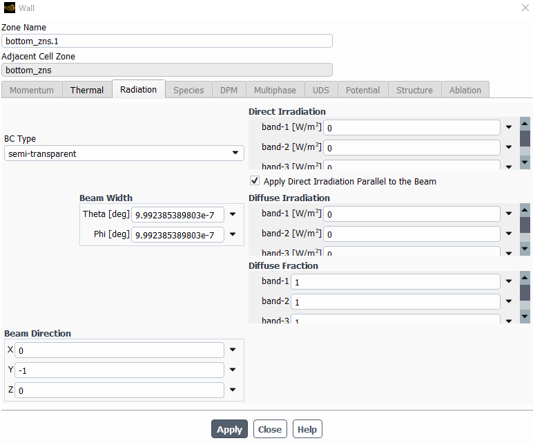
But when I change BC type of  a material A from opaque to semi-transparent in boundary condition - radiation tab,
I made four bands, 0 – 4, 4 – 8, 8-14, 14-1000 µm in Model - Radiation - Number of Bands = 4but I could only change Direct / Diffuse Irradiation and Diffuse Fraction of each band, not transmissivity or emissivity of each band.
Please, someone can guide me, it would be a great help,Is it possible to give each band different emissivities or diffuse fraction?
Or my assumption would be : diffuse fraction should be 1 , since reflection is zero ?
Â
-
March 26, 2024 at 5:22 amEssenceAnsys Employee
Hello,
For semi-transparent walls, Fluent automatically calculates the reflectivity and transmissivity from the refractive index of the material. You can input refractive index of the material on a per-band basis (choose refractive-band method) in the Material Create/Edit dialog box. Consequently the reflectivity and transmissivity are band-dependent.
For opaque walls, you can input band-dependent emissivity on the "Radiation" tab of the wall boundary condition dialog box. -
March 26, 2024 at 2:39 pmgopalakrishna.gangisettySubscriber
Â
Hello Mr. Essence,Â
Thank you very much for the response. I am using semi – transparent material and its emissivity is 0.25 for Long wave radiation, Refractive index is 2.2. I followed the instructions given by you. In the radiation tab, There is an option called beam direction where the default is X = 0, Y = 0 and Z = 1. I have an acceleration due to gravity set in Y direction = -9.81 m/s2. Then What is beam direction. Should it be X = 0, Y = 1 and Z =0 or X = 0, Y = -1 and z = 0 given the Y = acceleration due to gravity = 9.81 and this application for natural convection ?
Please kindly help me.Â
Â
-
March 28, 2024 at 4:14 amgopalakrishna.gangisettySubscriber
Thank you very much for the response. I am using semi - transparent material and its emissivity is 0.25 for Long wave radiation, Refractive index is 2.2. I followed the instructions given by you. In the radiation tab, There is an option called beam direction where the default is X = 0, Y = 0 and Z = 1. I have an acceleration due to gravity set in Y direction = -9.81 m/s2. Then What is my direction. Should it be X = 0, Y = 1 and Z =0 or X = 0, Y = -1 and z = 0 given the Y = acceleration due to gravity = 9.81 and this application for natural convection ?
Please kindly help me.Â
-
March 31, 2024 at 8:39 amEssenceAnsys Employee
Can you share the screenshot(s) of the panel you are referring to?
-
March 31, 2024 at 11:59 pmgopalakrishna.gangisettySubscriber
Hello Sir, Thank you for the reply and please find the screenshots below :Â
Given that the acceleration due to gravity is set in the Y-direction (g=−9.81 m/s2), indicating that gravity acts downwards, the positive Y-direction should be oriented upwards. Therefore, for natural convection modeling in this scenario, the direction of the beam for semi-transparent material should be X=0,Y=1, and Z=0 or X=0,Y= -1, and Z=0?Â
-
April 1, 2024 at 2:41 pmEssenceAnsys Employee
Â
Just a question. What is the range of temperature of your domain?
Â
-
April 1, 2024 at 2:48 pmgopalakrishna.gangisettySubscriber
Hello Sir,Â
At room temperature (298 K), the surrounding environment registers a temperature of 278 K. In our radiative heat transfer analysis, the objective is to dissipate heat from the building space to the surroundings, and subsequently to the cooler sky at 268 K. The skylight contains air and other greenhouse gases, and we aim to measure the transmitted radiative heat flux specifically within the wavelength range of 8 to 13 micrometers.
-
April 1, 2024 at 5:39 pmEssenceAnsys Employee
Thanks for the response. Please refer the Ansys guide link (section 5.3.6.7.5) for more information on beam direction and related topics.
https://ansyshelp.ansys.com/account/secured?returnurl=/Views/Secured/corp/v241/en/flu_th/flu_th_sec_mod_disco.html?q=beam%20direction
-
- The topic ‘How can I give different transmissivity with more than 3 wavelength region?’ is closed to new replies.
- Non-Intersected faces found for matching interface periodic-walls
- Unburnt Hydrocarbons contour in ANSYS FORTE for sector mesh
- Fluent fails with Intel MPI protocol on 2 nodes
- Help: About the expression of turbulent viscosity in Realizable k-e model
- Cyclone (Stairmand) simulation using RSM
- Mass Conservation Issue in Methane Pyrolysis Shock Tube Simulation
- Script Error
- Facing trouble regarding setting up boundary conditions for SOEC Modeling
- UDF, Fluent: Access count of iterations for “Steady Statistics”
- RIBBON WINDOW DISAPPEARED
-
1421
-
599
-
591
-
565
-
366
© 2025 Copyright ANSYS, Inc. All rights reserved.