TAGGED: compressible-flow-air, convergence-issues, nozzle
-
-
April 23, 2024 at 2:32 pm
lantonini
SubscriberHello everyone,
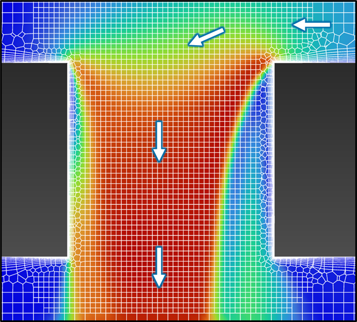
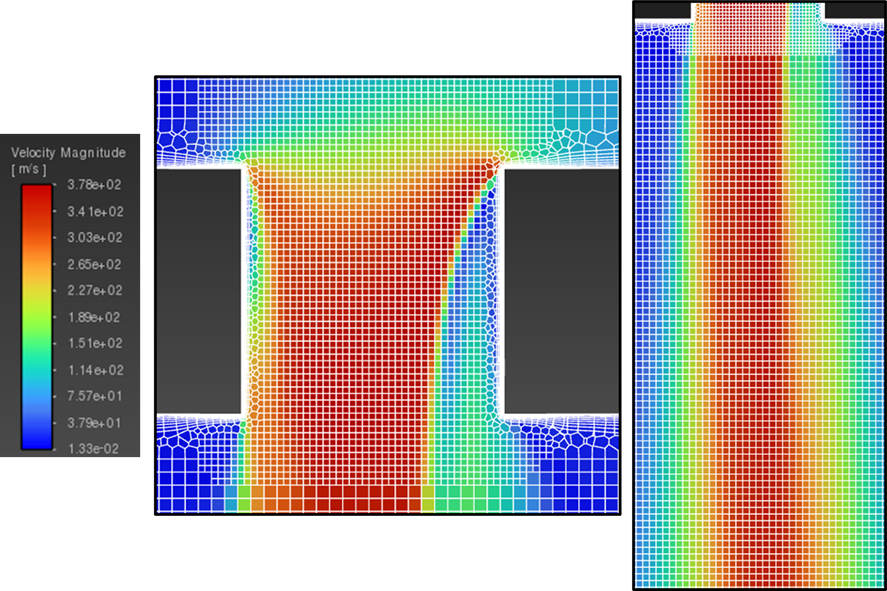
I'm currently conducting a simulation regarding a geometry where air enters a large tank through a small nozzle and then exits through a outlet hole.
Due to the high velocity of the incoming air and the small size of the inlet nozzle, the phenomenon under study cannot be described using incompressible gas models. Indeed, with such models, I was only able to achieve good agreement with my experimental data at low flow rates. However, at progressively higher flow rates with an incompressible gas model, I significantly underestimate the results in term of pressure losses.
However, when switching to describing the air as an ideal gas, I am facing some difficulties in achieving convergence in my analysis.
Currently, I am using the pressure-based solver, Coupled Scheme, and k-epsilon RNG turbulence model. Additionally, the preliminary results I am obtaining show significantly higher pressure losses compared to those recorded experimentally, with Mach numbers close to 1.
Do you have any suggestions on how to approach this problem? Should I reconsider some of my assumptions to better describe the behavior of air at these flow regimes?
Thank you all in advance.
-
April 24, 2024 at 1:03 pm
Rob
Forum ModeratorLook at the turbulence models a little more carefully: do you think RNG is the best choice for jetting flow? Is the system single phase? How much mesh have you got around the jet?Â
-
April 24, 2024 at 2:34 pm
lantonini
SubscriberThank you for showing interest in my analysis.
The choice of the turbulence model was guided by a literature review, where I found that k-epsilon RNG and k-omega SST models were commonly used for similar applications.
Should I use a different model?
My system consists of a single phase, air, and I am attaching an image showing the detail of the mesh, representing the Velocity Magnitude color map.
I'm using a hexcore mesh considering 8 boundary layers.
Specifically, in the image, I have zoomed in on the area where the air is moving from the inlet tube (at the top with flow from right to left) to the tank (at the bottom).The flow direction is indicated by the arrows.
-
April 24, 2024 at 2:50 pm
Rob
Forum ModeratorOK, you look to have resolved the geometry nicely with the mesh, but you also need to resolve the flow. So you may need more mesh in the jet region just off the bottom of the image.Â
Please replot with node values off, and also include the scale.Â
You may want to read this  /knowledge/forums/topic/ansys-fluent-compressible-flows-tips-and-tricks-presented-on-2-12-2019/Â
Â
-
April 24, 2024 at 3:14 pm
-
April 24, 2024 at 3:34 pm
Rob
Forum ModeratorLooks OK. How does the Mach Number plot look?
What boundary conditions are you using?
-
April 24, 2024 at 3:50 pm
lantonini
SubscriberHere I have represented the Mach Number.
I am working trying Mass-Flow Inlet - Pressure Outlet and Pressure Inlet - Pressure Outlet, but in both cases, the results tend to overestimate my experimental curve of pressure loss - flow rate at high flow rates.
Since the tank outlet pipe reaches the open air, I'm imposing Gauge Pressure of 0 Pa at the Outlet and 101325 Pa as Operating Pressure.
Also I'm using Intensity [5%] and Hydraulic Diameter method at the boundaries. -
April 24, 2024 at 4:01 pm
Rob
Forum ModeratorWhat's the (supersonic) inlet pressure? Looking at the Mach Number plot you may need some more refinement, difficult to say. Have a look at region refinement (adaption).Â
-
April 24, 2024 at 4:23 pm
lantonini
SubscriberSince at low flow rates the results were good I've always left the Supersonic/Initial Gauge Pressure equal to 0 Pa.
How should I evaluate a good value for this quantity?
-
April 25, 2024 at 10:47 am
Rob
Forum ModeratorWhat pressure is the upstream condition? It's covered in the manual (click on Help on the boundary condition panel) but try setting the same as the inlet condition.Â
-
April 29, 2024 at 1:35 pm
lantonini
SubscriberI'm considering pressures between 20'000 Pa and 140'000 Pa. But, since my inlet area is grater than the nozzle one, the flow is subsonic at the inlet. In this condition, the simulations should not be affected by the value of Supersonic/Initial Gauge Pressure, right?
-
April 29, 2024 at 2:14 pm
Rob
Forum ModeratorPossibly. You may then need to patch the region above the nozzle to the correct pressure. Fluent needs to know the upstream pressure to get the density right, which then alters the flow field.Â
-
- The topic ‘High-Velocity Air Flow Through Small Nozzle into Large Tank’ is closed to new replies.
- How do I get my hands on Ansys Rocky DEM
- Non-Intersected faces found for matching interface periodic-walls
- Unburnt Hydrocarbons contour in ANSYS FORTE for sector mesh
- Help: About the expression of turbulent viscosity in Realizable k-e model
- Script Error
- Mass Conservation Issue in Methane Pyrolysis Shock Tube Simulation
- Facing trouble regarding setting up boundary conditions for SOEC Modeling
- convergence issue for transonic flow
- Running ANSYS Fluent on a HPC Cluster
- Point exception in erosion calculation
-
1902
-
807
-
599
-
591
-
366
© 2025 Copyright ANSYS, Inc. All rights reserved.