

-
-
June 21, 2021 at 5:28 am
omnia.nawwar
SubscriberHello,
I am trying to simulate high Q ring resonator using varFDTD. In experiment, we have a Q factor of about 10e6 with critical coupling distance of 400nm. So this is a high Q resonator.
June 25, 2021 at 12:41 amKyle
Ansys Employee
Q factor calculations can be very difficult, especially for high Q structures. It looks like you need to increase the simulation time even more to get reliable results.
Instead of using FDTD for this simulation, it is generally better to use INTERCONNECT for large ring resonator simulations as described on this page: /forum/discussion/27337/how-to-include-propagation-loss-and-coupling-coefficient-in-ring-resonator/p1
This is the approach used in our ring modulator and CROW filter examples:
If you don't have a license for INTERCONNECT, another more efficienct approach might be to use FDTD to get the coupling coefficients as a function of gap distance and the mode properties with the FDE solver in MODE, and put this into an analytical ring resonator model to get the Q factor. An analytical formula for the Q factor of a single bus ring resonator is given in: Bogaerts, Wim, et al. "Silicon microring resonators." Laser & Photonics Reviews 6.1 (2012): 47-73.
June 25, 2021 at 12:51 amSubscriberI cannot use interconnect in my case as I am using sampled material data . I insert the index of the material myself. Is there a way to do the same in interconnect. I think the ring in interconnect is for Si ring only. Right?
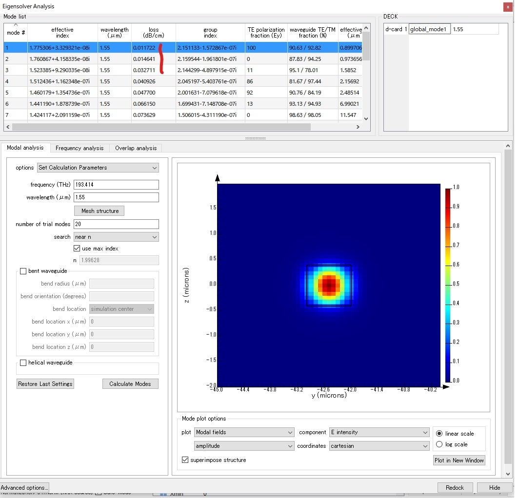
Another question please. I am using a lossless material data with imaginary index value of zero. However, when calculating the modes, I have a loss value in the "Eigensolver Analysis" mode list starting from 0.011722dB /cm for straight waveguide and increase as I do bend analysis.
How this loss value can be interpreted with index imaginary part of material equals to zero.
June 25, 2021 at 4:58 pmAnsys Employee
INTERCONNECT doesn't use material data. INTERCONNECT uses the results from the component solvers (FDTD and MODE), such as effective index and coupling coefficients, it doesn't perform the physical simulation itself. As long as you use the correct material data in your FDTD and MODE simulations, you can use INTERCONNECT to simulate a photonic circuit made with any material.
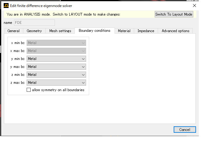
Can you please give some more details on your FDE simulation? Is it a leaky mode? Do you include a high-index substrate in the FDE simulation region? What boundary conditions are you using? If you have a high index substrate, or you're simulating a leaky mode, there could be losses due to radiation. However if you have a bound mode, these could be artificial losses from the PML boundary conditions being too close to the waveguide core. In this case you should use metal BCs and increase the span of the simulation region.
June 28, 2021 at 3:01 amSubscriberMy FDE simul;ation for confined mode. BCs are all metal. The waveguide is Si3N4 with SiO2 as clad and BOX.
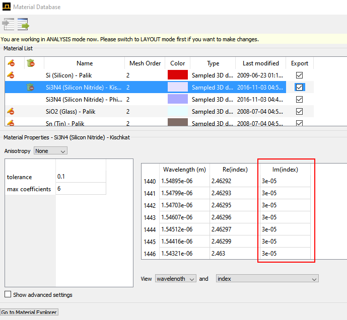
June 29, 2021 at 12:19 amAnsys EmployeeThank you for the screenshots. If you are using metal BCs then the losses must be through material absorption. If you look at the material data for the Kischkat Si3N4 in the Material Database you can see that the imaginary part of the index is non-zero:
 This is where the losses are coming from in your simulation. If you would like to simulate a lossless material, you can specify the index directly by selecting "June 29, 2021 at 12:58 amSubscriberThank you for you fast response. I am using a customer defined material with a real index changing with wavelength and zero imaginary index as you can see in the screen shot below. The plan was to study a lossless material in the simulation and then insert the imaginary part and see the difference.
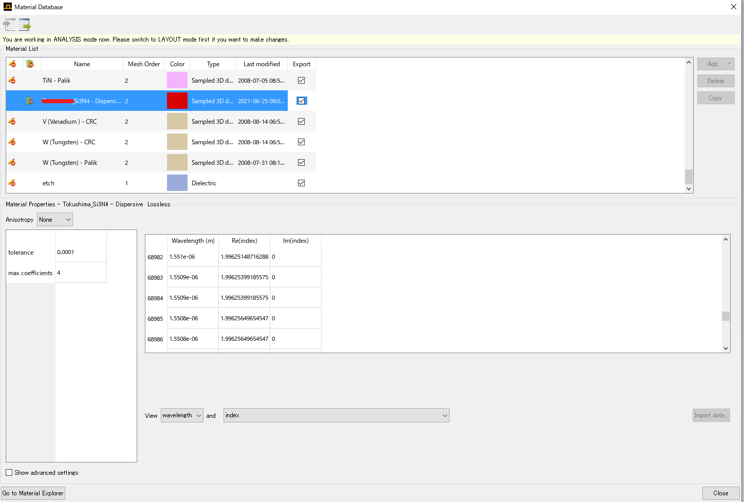
June 29, 2021 at 1:22 amAnsys EmployeeWhen you visualize the material data in your simulation is it zero? For example, after meshing the structure:
 What does the material fit look like? You can plot the material fit in the Material Exploter:
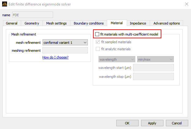
 Do you have the "fit materials with multi-coefficient model" option of the FDE solver object turned on?
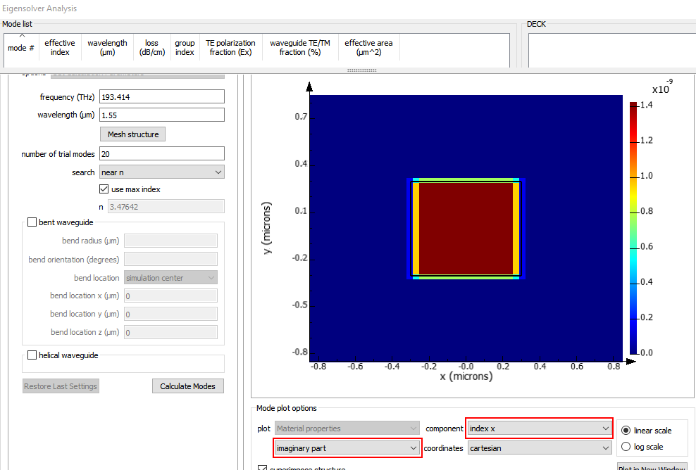
July 2, 2021 at 1:44 amSubscriberI checked the imaginary part again in FDE window and here is the results
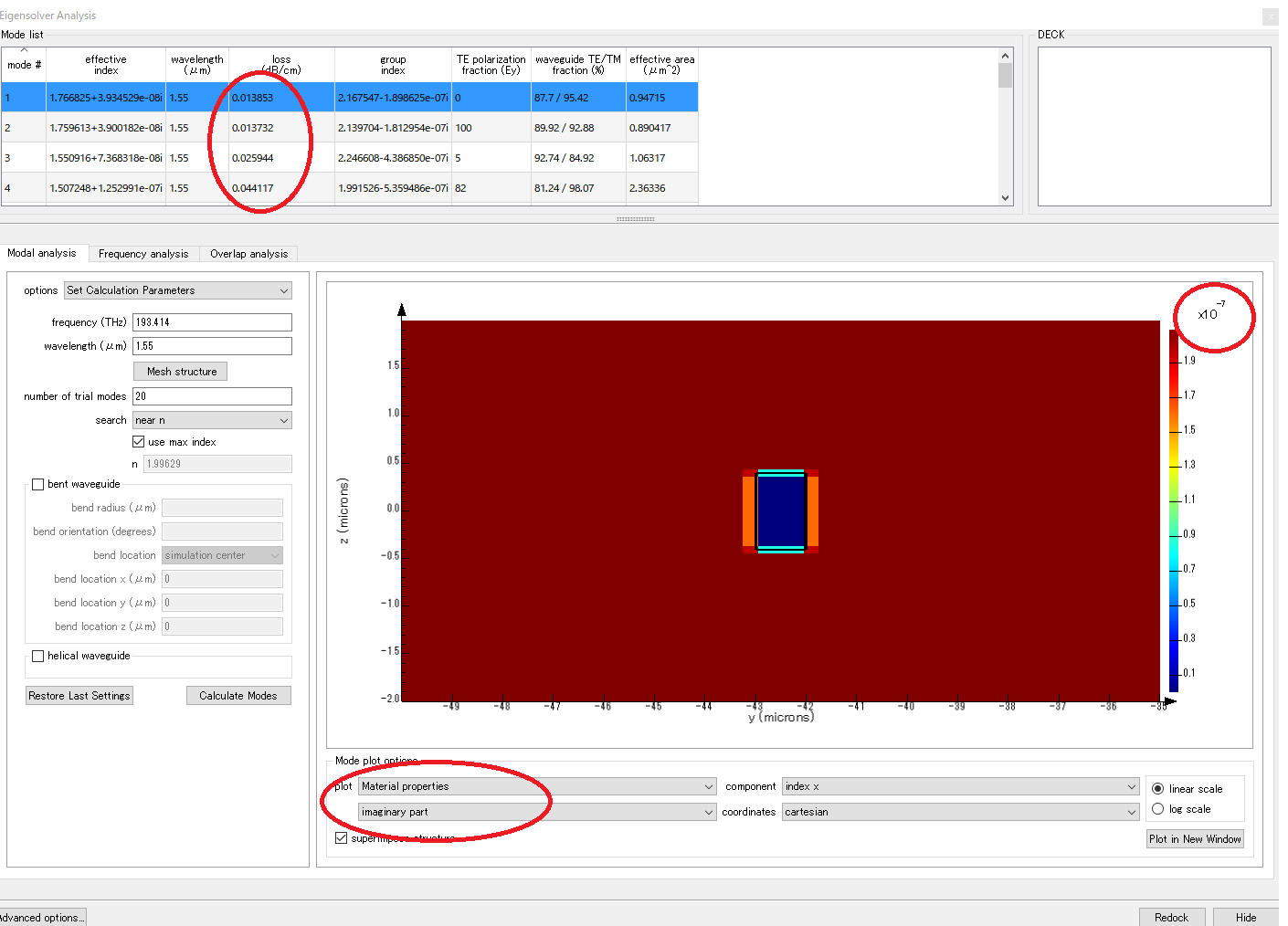 Yu can see the imaginary part is multiplied by 1e-7 while I still have the mode loss in the mode list.
July 2, 2021 at 5:16 pmAnsys Employee
Thank you for the screenshots. It looks like the cladding/substrate has a non-zero imaginary refractive index, which is what's leading to this loss. If you're using a fitted material there might be a small imaginary refractive index in the fit even if it's not present in the data. You can check the material fit in the Material Explorer. Instead of a fitted material, you can use index values interpolated between the material data points by turning off the "fit materials with multi-coefficient model" option of the FDE solver object(see my previous post).
You could also remove this loss by replacing the cladding/substrate material with a material with constant refractive index (for example anJuly 9, 2021 at 4:22 amSubscriberThank you so much for your help. looks like it is the source of this loss
Viewing 10 reply threads- The topic ‘high Q ring resonator ring-bus sweep’ is closed to new replies.
Innovation Space Trending discussions
 Top Contributors
-
peteroznewman
 4167
4167 -
scabo
 1487
1487 -
Dennis Chen
 1363
1363 -
javat33489
 1194
1194 -
Shyam Prasad V Atri
1021
Top Rated Tags
© 2025 Copyright ANSYS, Inc. All rights reserved.
Ansys does not support the usage of unauthorized Ansys software. Please visit www.ansys.com to obtain an official distribution.
-


The Ansys Learning Forum is a public forum. You are prohibited from providing (i) information that is confidential to You, your employer, or any third party, (ii) Personal Data or individually identifiable health information, (iii) any information that is U.S. Government Classified, Controlled Unclassified Information, International Traffic in Arms Regulators (ITAR) or Export Administration Regulators (EAR) controlled or otherwise have been determined by the United States Government or by a foreign government to require protection against unauthorized disclosure for reasons of national security, or (iv) topics or information restricted by the People's Republic of China data protection and privacy laws.


