TAGGED: cfd-post, volume-of-fluid
-
-
June 30, 2023 at 12:17 pm
Dubey92
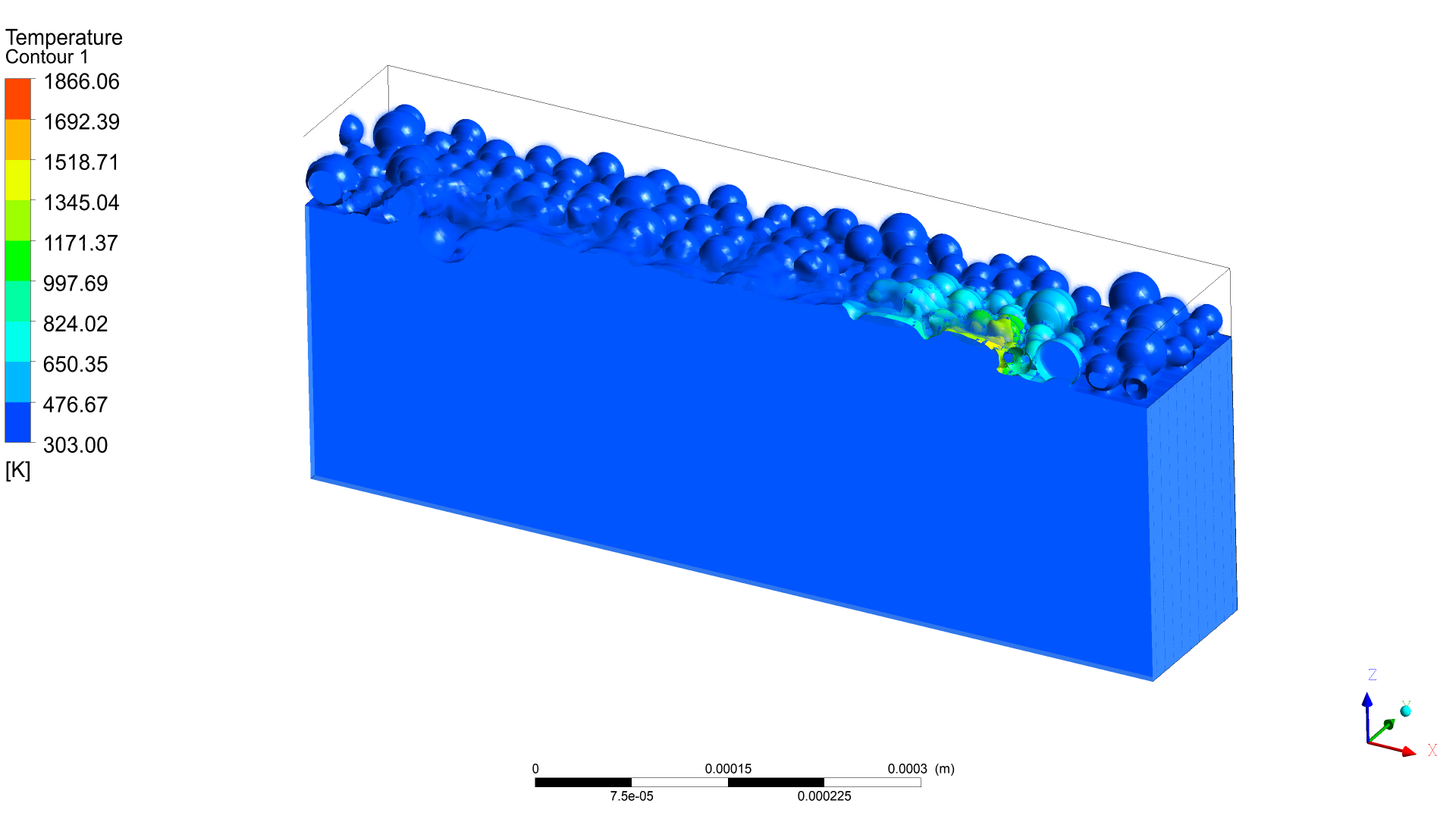
SubscriberI am modelling laser melting in FLUENT. After my simulation I am trying to visualise it in CFD-Post. My results are not visible upto the mark. In the figure below, the there are metal particles above a solid metal base. I have used isosurface and volume rendering for metal phase (it is a multiphase flow with two phase-air and metal). But the results don't look very promising.
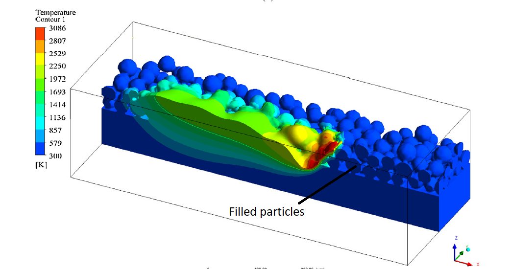
The imgae below is from a published paper and they have also used CFD-Post but their results look very good. Can someone pleae help where I might be committing mistake?
-
July 3, 2023 at 9:13 am
Rob
Forum ModeratorAre you displaying temperature on the surface, or a contour of a surface whilst displaying the surface? The lower image looks to be temperature on an iso surface of VOF and a clip on the side faces of the region that's in the melting phase.
-
July 3, 2023 at 11:02 am
Dubey92
SubscriberThanks for your reply Rob. The first image is mine. First I plotted the iso-surface for volume fraction(at 0.5) of metal phase. Then I am showing temperature contours on that iso-surface. I am unable to understand how the second image is showing it on the cut cross-section also.
-
-
July 3, 2023 at 11:19 am
Rob
Forum ModeratorIf you just show the contour does it fill the lower section too? CFD Post and Fluent multiphase can have issues, you may find you're better doing the post processing in Fluent to understand what's going on. Execute Commands is your friend there - it means you can spit out images every some time steps.
-
July 3, 2023 at 11:28 am
Dubey92
SubscriberNo. When I plot the temperature contours in the iso-surface, it does not fill the lower section. I think the second image is also from CFD-Post. Also, can you tell how the particles are more defined and filled in the second image. I have also used volume rendering in my case but they don't look that good.
-
-
July 3, 2023 at 12:44 pm
Rob
Forum ModeratorI suspect the sharper image is down to lighting, possibly linked to a better resolution mesh.
Volume rendering is intended to show stuff in 3d, so in your case the cold regions may mask the rest. The original intent was to show smoke - think how that looks in the real world.
-
July 3, 2023 at 1:07 pm
Dubey92
SubscriberActually the mesh resolution is same. But can you suggest something about the contours? How to show the contours like the second image at the cross-section also?
-
-
July 3, 2023 at 1:39 pm
Rob
Forum ModeratorI suspect the cross section is a plane, which is then clipped to iso-value of VOF and then coloured by temperature.
-
July 3, 2023 at 4:48 pm
Dubey92
SubscriberOhh. Maybe. I will try it. Thanks
-
-
July 19, 2023 at 7:55 am
Jian Liu
SubscriberHello, I have been following your field of study. I tried to use the VOF model in the fluent software to simulate the laser melting material, consisting of two phases (air and metal), turning on the energy and melting and solidification parameters1. I tried to do what you did (using a Gaussian surface heat source on the XY plane, r = sqrt(pow(x[0],2.0) + pow(x[1]-y0,2.0), as shown in Figure 1), according to the UDF you are using multiplied by the C_UDMI(c,t,3) gradient after the Gaussian distribution, but the same Gaussian distribution is shown in the XZ plane, I hope that only the second phase is subjected to the heat source (the heat source acts on the metallic phase), please ask you this step (if(C_VOF(c, t)>0.05 && C_VOF(c,t)<1)) Does it allow me to achieve my purpose?I am very grateful for any reply, loyal thanks!-
July 22, 2023 at 9:22 am
Dubey92
SubscriberWhen you use the C_UDMI(c,t,3), it applies the source only in the phase for which you are targetting.
-
-
July 19, 2023 at 8:15 am
Rob
Forum ModeratorI'll let Dubey92 comment on their work.
As a comment. Fluent's radiation models see only what's in the mesh cell, there are no additional terms in the model(s) for free surface effects. So, the only way to heat the metal part is to have a high absorption coefficient and/or (I've not read their work) use UDFs to mimic a free surface effect.
-
July 21, 2023 at 2:42 am
Jian Liu
SubscriberThank you for your efforts.
Or I would say that in the VOF model, how to load the surface heat source between the two phases? Do I need to use a volume fraction gradient?
-
-
July 21, 2023 at 8:52 am
Rob
Forum ModeratorI think you'd need some coding.
-
July 22, 2023 at 6:32 am
Jian Liu
SubscriberOk, thank you a lot.
I'll keep trying
-
-
- The topic ‘Help with post processing’ is closed to new replies.


-
3492
-
1057
-
1051
-
965
-
942

© 2025 Copyright ANSYS, Inc. All rights reserved.


