

TAGGED: -adaptive-mesh
-
-
July 4, 2025 at 10:41 am
19251758
Subscriber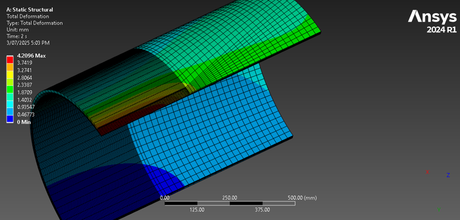
Without fillet as in the high stress edges in defected pipeline above, the accuracy of the simulation is low. On adding fillet to mitigate the high stress edges/ sigularuty effect I struggle to get a hexahedral mesh, please I need the steps to achieve that.
Kind regards
Martin
-
July 4, 2025 at 1:01 pm
peteroznewman
SubscriberIn SpaceClaim, split the body into solids that are easily hex meshed and a solid that has the fillet. On the Workbench tab, use the Share button to keep the mesh connected across the bodies by sharing nodes on the split faces. In Mechanical, right click on the bodies to be hex meshed and mesh those first. Mesh the fillet body last with tet elements.
-
July 7, 2025 at 12:18 amSubscriber
Thank you kindly Peter for the modeling suggestion. With the 5mm fillet, I have 1/4 defected pipe divided into sweepable parts. I do not know why I am still having error messages in trying to hexa mesh this. Please I still need your help.
Kind regards
Martin
-
July 7, 2025 at 2:21 pmSubscriber
Upload your .scdoc file to a file sharing site and reply with the link. If using Google Drive, make sure to Share so that Anyone with the Link can download it and not leave it at the default Restricted share setting which means no one with the Link can download it without first getting permission from you.
-
July 8, 2025 at 1:27 am
-
July 8, 2025 at 1:32 amSubscriber
Good morning Peter,
Please find the link to the quarter pipe in Ansys spaceclaim above.
Kind regards
Martin
-
July 8, 2025 at 12:40 pmSubscriber
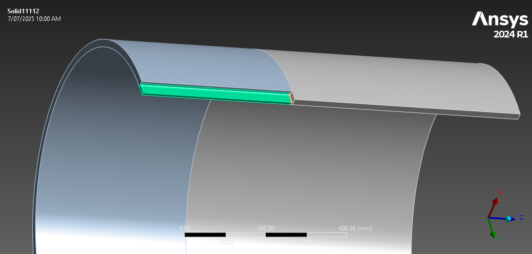
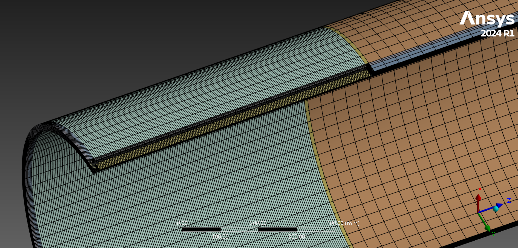
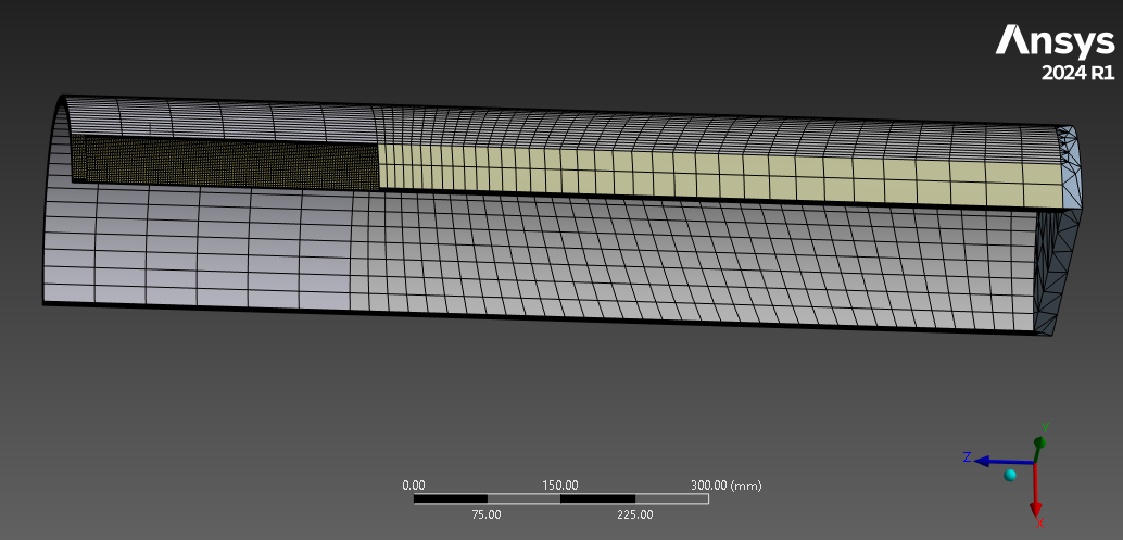
I don’t have access to 2024 R1, so I have meshed this in 2025 R1. Notice how I have used parallel planes 5 mm on either side of the fillet.
A finer mesh can be put on the fillet, by using twice as many elements through the thickness of the rest of the body.
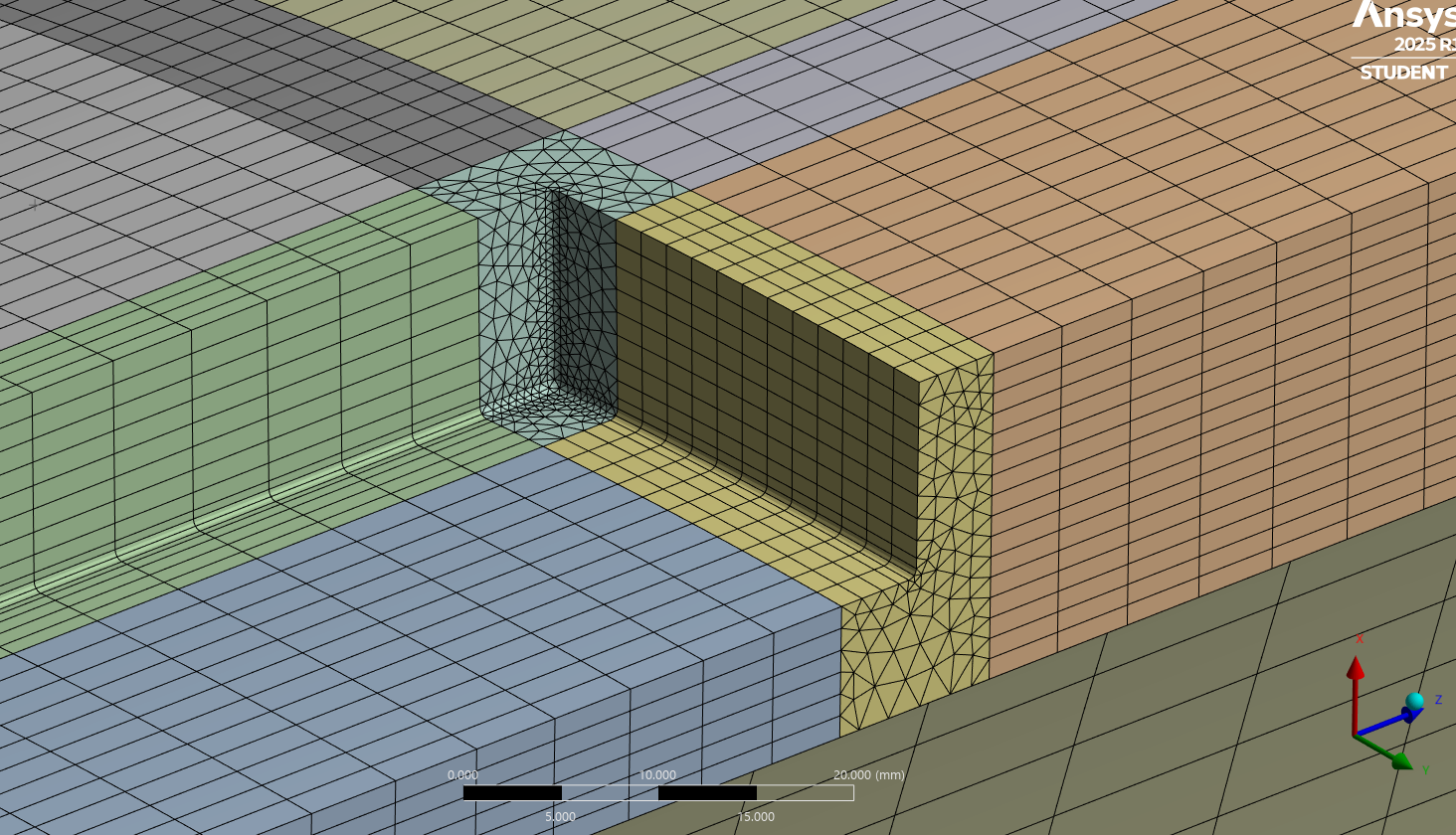
To put a finer mesh on the fillet add face sizing to the fillet. Selective order of meshing can sometimes create more hex elements on the extruded shape.
Adding a Hex Dominant Method to the fillet block.
-
July 9, 2025 at 2:24 amSubscriber
Good morning Peter,
Thank you kindly for solving this problem that has been a challenge, I will carefully follow the steps you explained and try to achieve the same result. But please could you save the file in a lower version (2024 R1) and share the link.
Kind regards
Martin
-
July 9, 2025 at 2:27 amSubscriber
Otherwise I can download the student version of 2025 R1.
Kind regards
-
July 9, 2025 at 7:21 amSubscriber
Good afternoon Peter,
I have done some meshing but still trying to improve the accuracy, please see below. When I applied refinment at the fillet, the removes the entire hex mesh.
Kind regards
-
July 9, 2025 at 3:07 pmSubscriber
Hello Martin,
Ansys can’t save projects as older versions of the program. Here is a link to the Ansys 2025 R1 archive. https://jumpshare.com/v/CoTzIWqIgxwkPIYAr4Mx
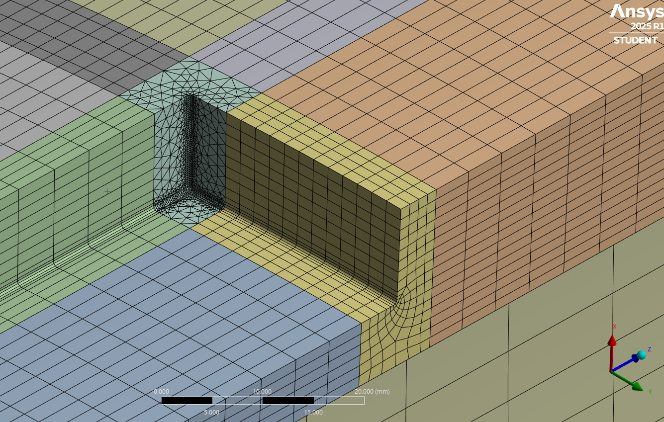
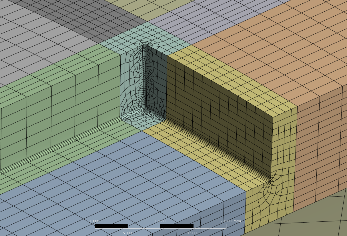
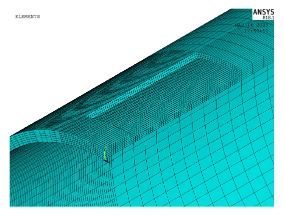
You will see that I use Edge Sizing mesh controls to force the mesh to stay aligned by choosing the Hard option and selecting all the edges that I want to stay aligned.
Though more hex elements are created at the surface using the Hex Dominant method on the fillet corner solid, there are some skinny elements below the surface that allow hex elements at the surface.
Regards,
Peter -
July 31, 2025 at 5:00 amSubscriber
Good afternoon Sir,
Please I have been working on this particular model to improve the mesh element quality yet it appears the meshing has not improved whenever I check in the mesh metric, please I need some help.
-
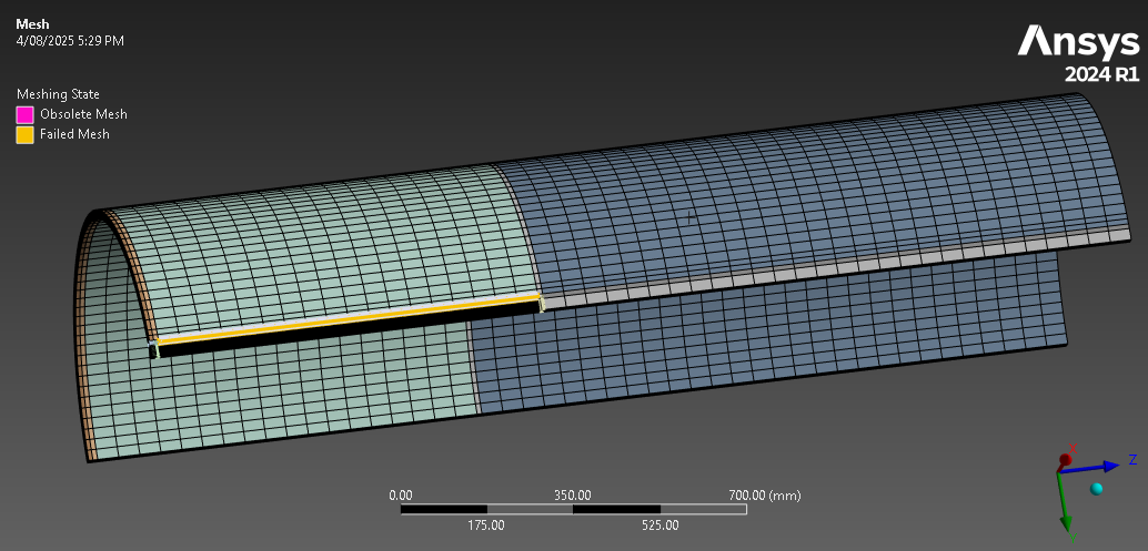
July 31, 2025 at 5:29 amSubscriber
Good afternoon Sir,
After splitting the interacting defected pipeline, most of the solid parts were sweepable apart from 2 parts.
I do not understand why I am getting poor quality mesh. Please find the pipe attached here-in.
https://drive.google.com/file/d/148jbore67vbSY1mCLOLdwUfgiDDe7I7Y/view?usp=sharing
https://drive.google.com/file/d/148jbore67vbSY1mCLOLdwUfgiDDe7I7Y/view?usp=sharing
Kind regards
Martin
-
July 31, 2025 at 2:18 pmSubscriber
Hello Martin,
You should show where the poor quality elements are using the Mesh Metric function.
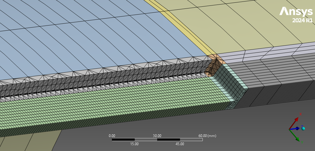
A plane used to split the solid created sliver faces which can lead to poor element quality.
Some mitigation can be done in Mechanical by inserting Virtual Topology to merge those faces, however, VT caused the gray body that was originally sweepable to become not sweepable.
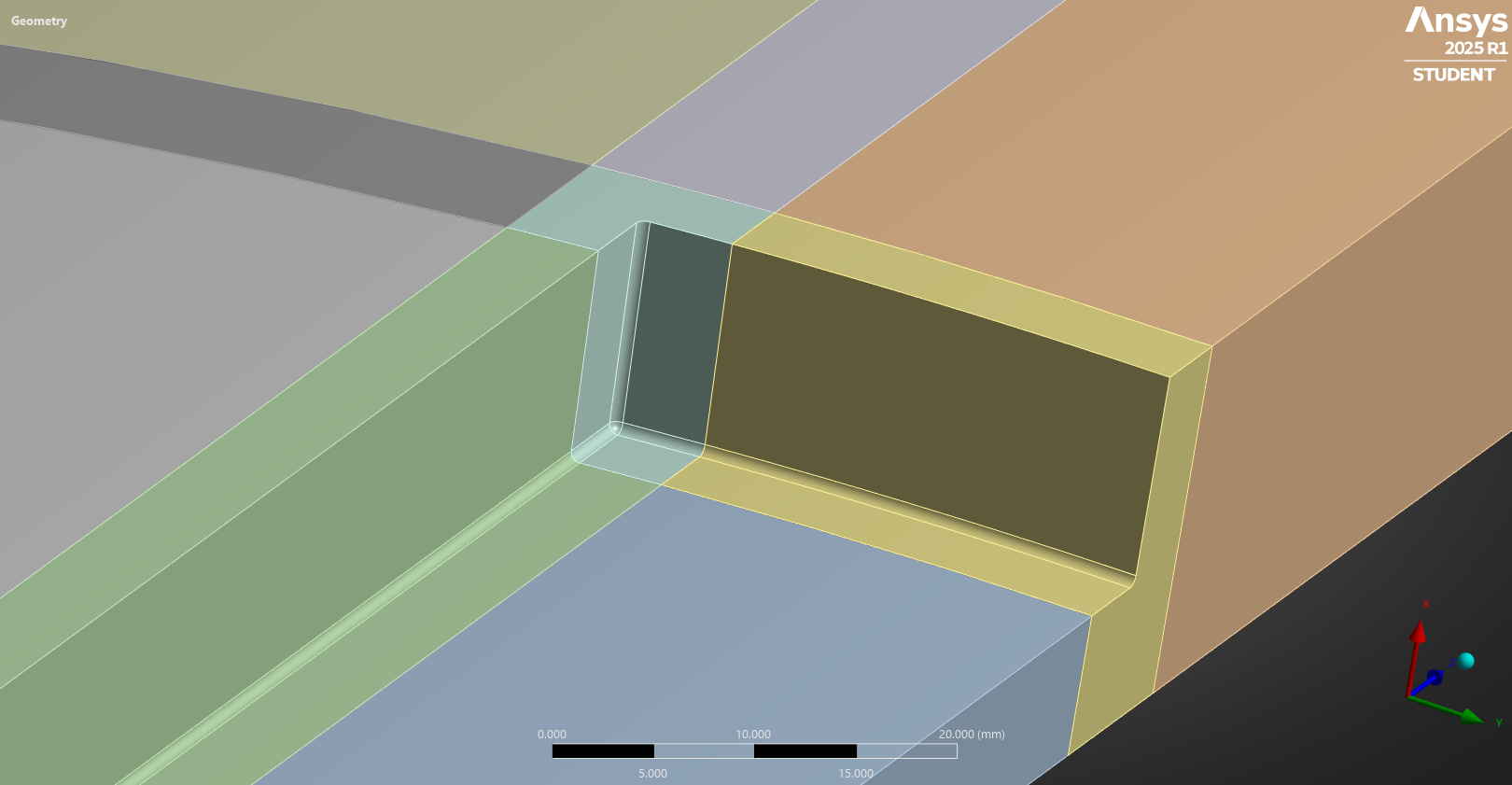
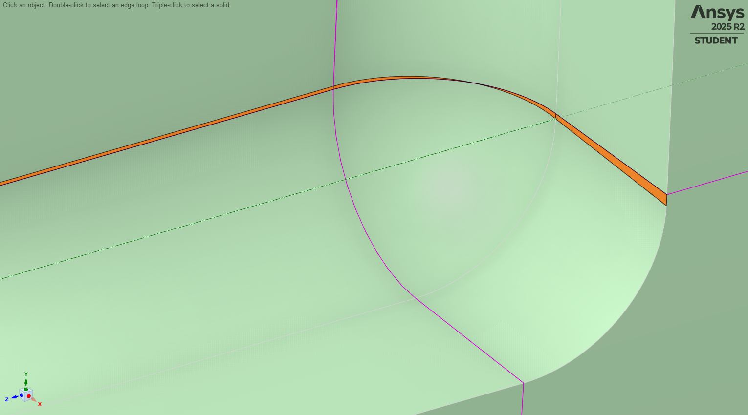
I recommend you go back to SpaceClaim and more carefully create planes to split the solid such that no sliver faces are created. After I Combined some solids into one body and used a more precise horizontal split plane, when I tried to reuse a vertical split plane, new inaccurate faces were created as can be seen in the image below.
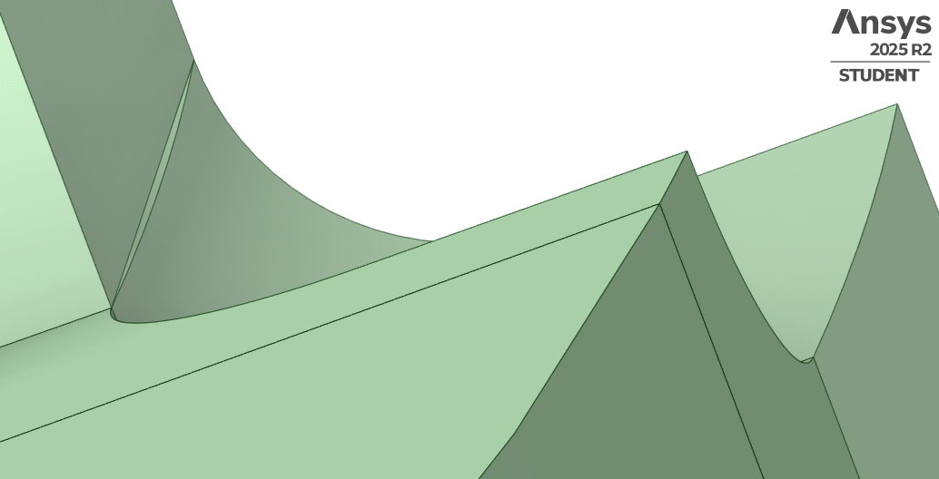
My suggestion is that you locate the split plane a short distance away from a blend edge. Don’t locate a split plane coincident with a blend edge.
-
August 4, 2025 at 5:44 amSubscriber
Good afternoon Sir,
Thank you kindly for all your response, I am grateful. I have placed the split plane away from the blend edges as adviced, please find the link attached here in.13 sweepable bodies out of 15 solid parts were confirmed. At the Ansys mechanical, after setting the symmetric region, I right clicked on mesh, pressed the mesh start record button and started generating hex mesh for all the sweepable parts, element size for areas away from the defect were made coarse. At the defect area, I made use of edge sizing to achieve the needed element size.
I am still having issues with my meshing, please can I get your advise on the steps to complete the meshing with good element quality. The meshing I did, the element quality was poor, mostly less than 0.2.
Kind regards
Martin
https://drive.google.com/file/d/1G6-FhNpD8qZCoEZHOQe7FBfvU_aau0gt/view?usp=sharing
-
August 4, 2025 at 7:33 amSubscriber
I received the following warning;
Some of the elements on the problematic bodies can't meet the specified target metrics. Please check the elements and try changing the mesh size settings to achieve the needed mesh quality.
The surface mesh is intersecting or close to intersecting, making it difficult to create a volume mesh. Please adjust the mesh size or adjust the geometry to fix the problem.
Kind regards
Martin
-
August 4, 2025 at 12:45 pmSubscriber
Hello Martin,
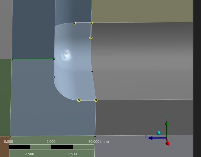
I am using Ansys 2025 R2 so you may or may not see exactly the same in Ansys 2024 R1. Below is what I see in Mechanical when I open the Aug-04-2025.scdoc file.
Notice that the Show Vertices and Close Vertices are turned on in the Display ribbon.
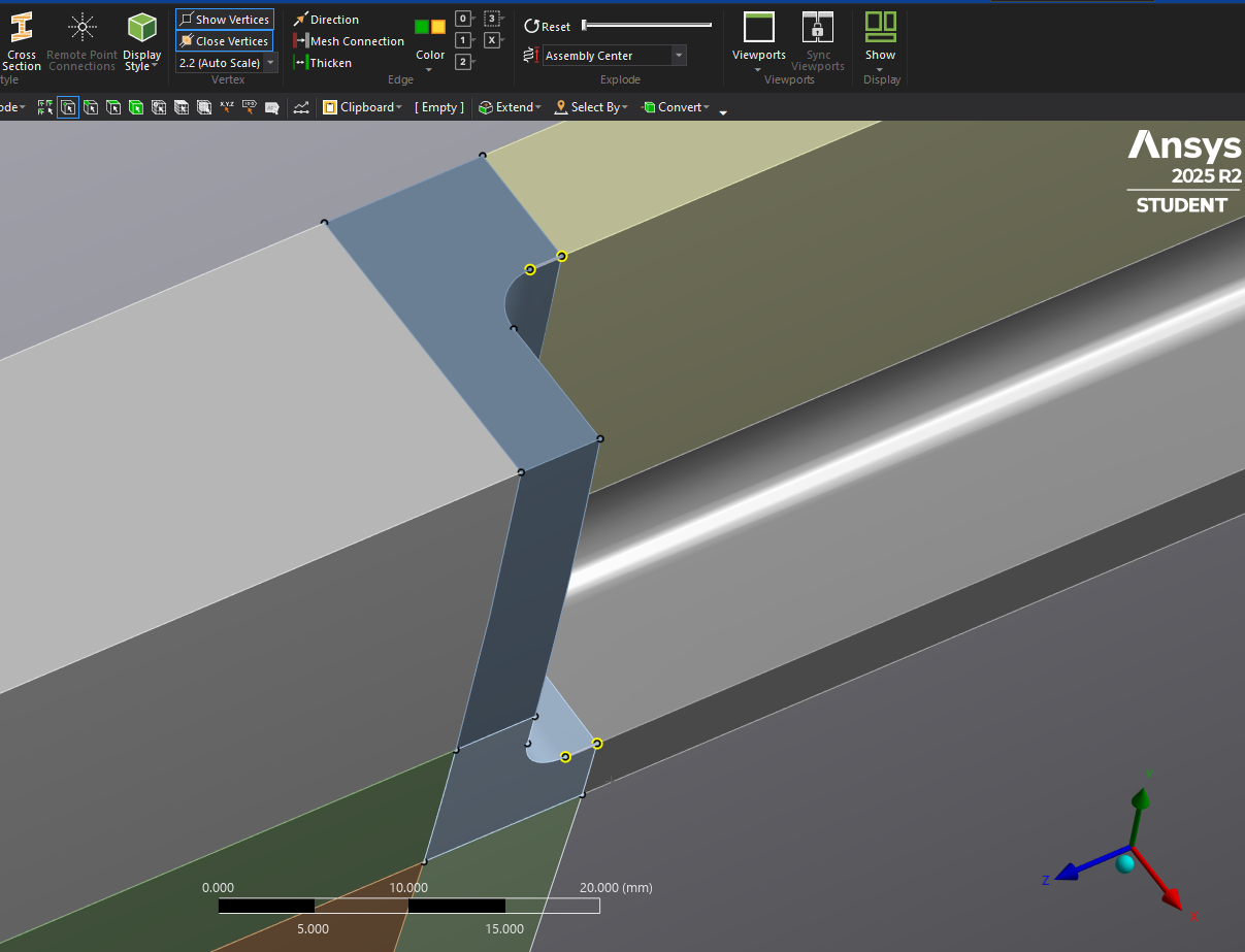
The close vertices are highlighted in yellow. This is feedback to you that the geometry is not clean. You should not have any close vertices. However, the mesher is often clever enough to ignore them.
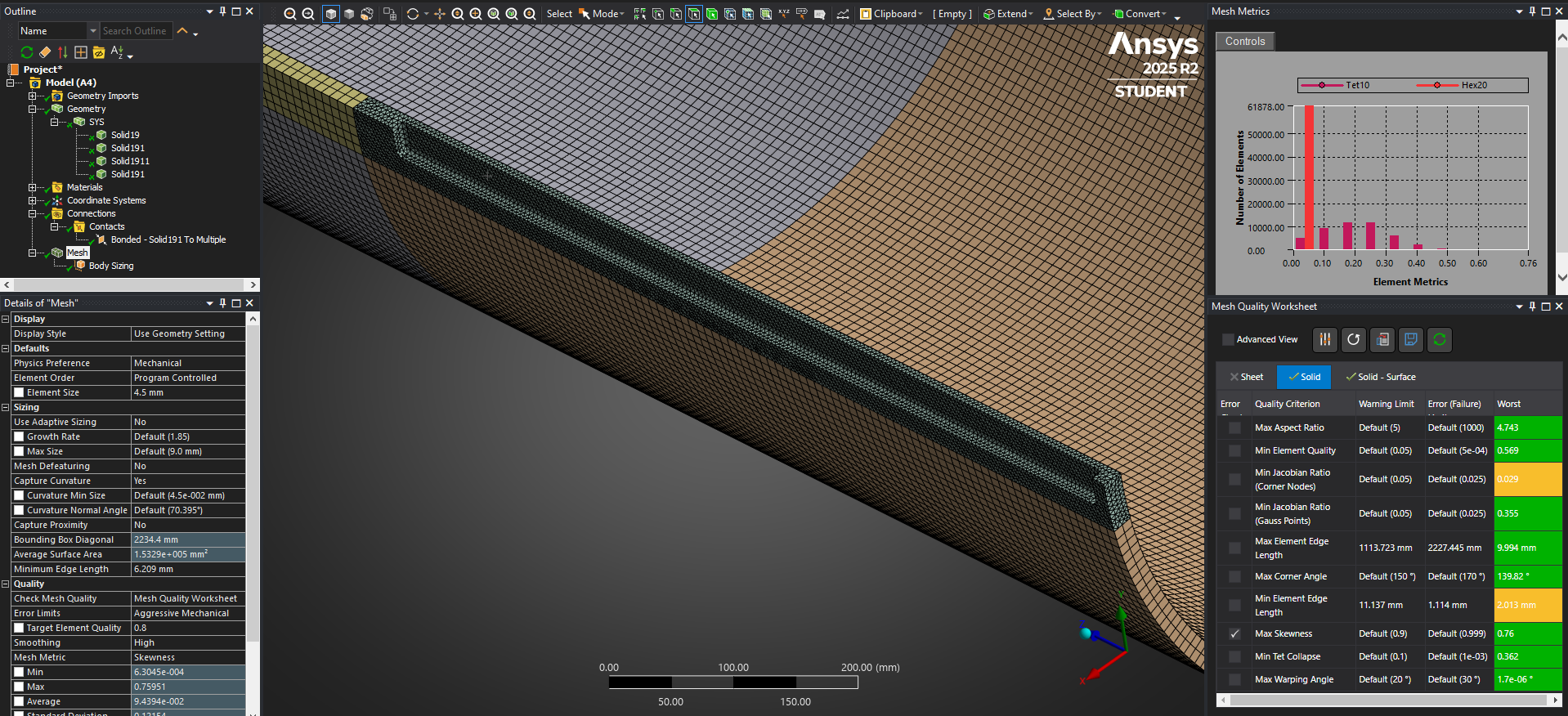
In Ansys 2025 R2, there is a Mesh Quality Worksheet. I wouldn’t pay attention to the red bar with the Minimum Element Edge Length. That is not the cause of any poor element quality.
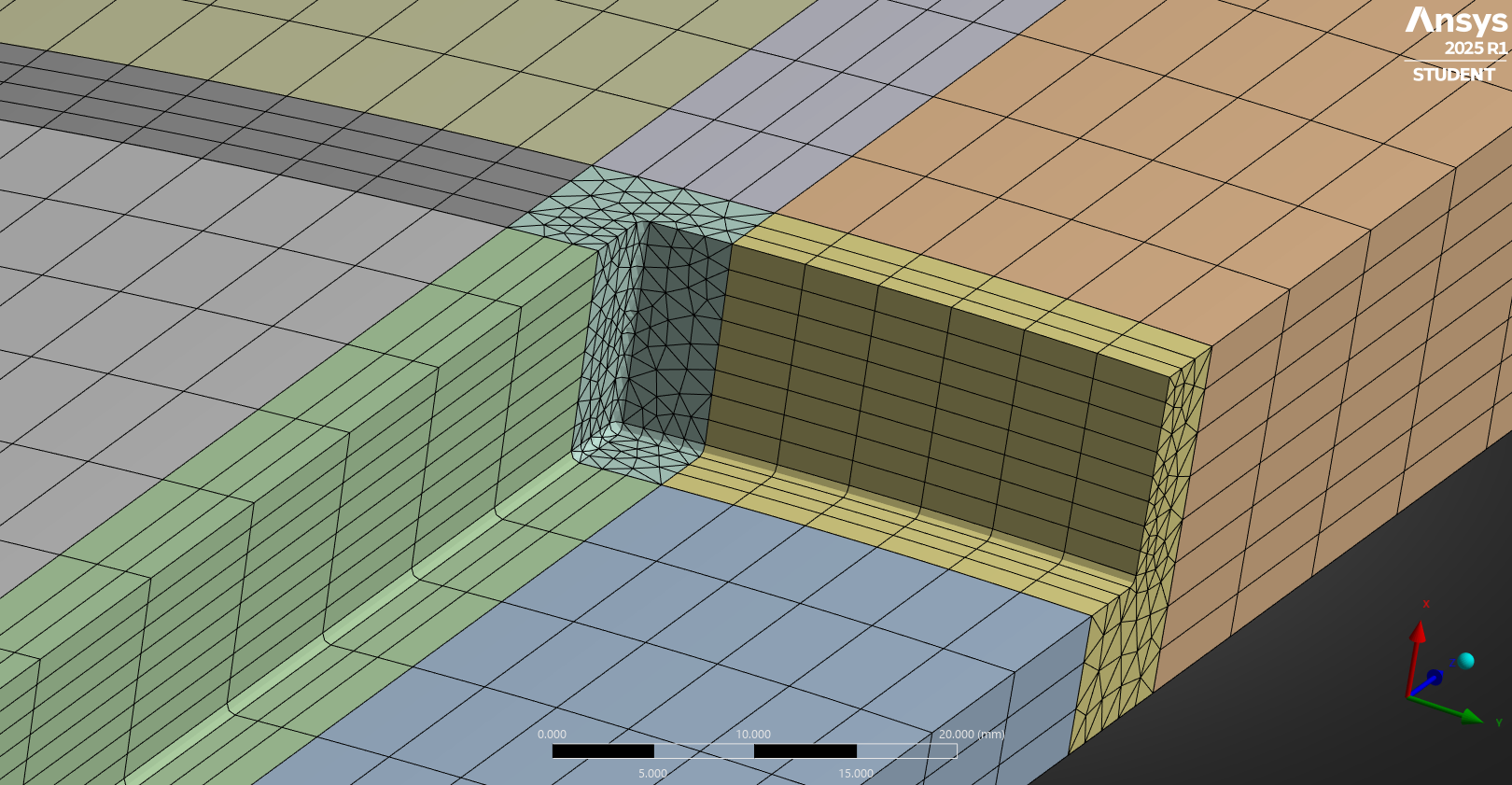
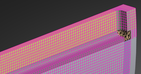
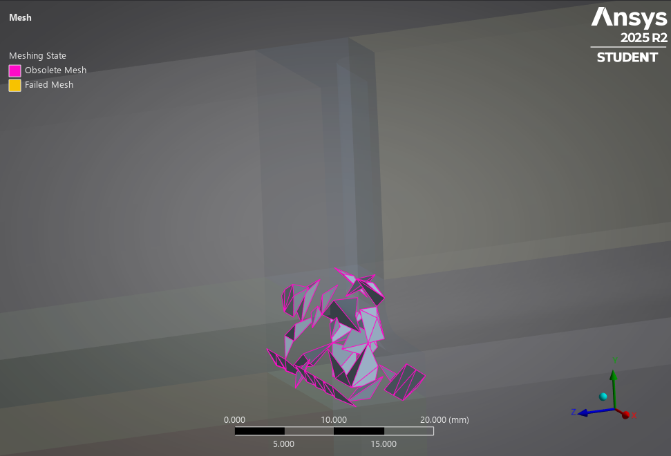
The warning limit for Max Skewness is 0.9 and this mesh has a Max value of 0.99892. Elements over 0.9 are highlighted here: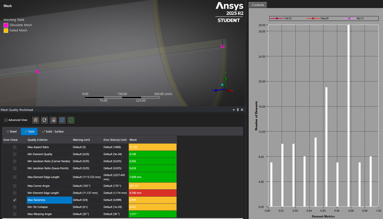
Zooming in you can see that the tet elements in the corner are the problem.
You have a 5 mm setback from the blend to the plane to slice out the sweepable part. If you increase that to 15 mm, you might leave sufficient space to allow the elements to mesh with better quality.
A good approach here would be to use just 2 planes to cut the slot out for Tet meshing with an element size of 4.5 mm on that solid, while the other three hex meshed solids have a Body sizing of 9 mm. These values ensure that 2 quadratic elements are across every section of the model, which is the minimum recommended number. Bonded contact keeps the two cut faces on the slot solid bonded to the other two solids.
In SpaceClaim, hide the slot solid and use the Share button to keep the mesh connected on the three bodies with the Hex mesh so you don't need Bonded contact on those faces.
-
August 12, 2025 at 4:55 amSubscriber
Good afternoon Sir,
Thank you kindly as always for your assistance in my modeling. Please sir, I wanted to use the last approach to model the defected pipe attached below, here hexahedral is used for the meshing of the entire corroded pipe. Tetrahedral only used for rigid body meshing. 3 layers of elements at the defect region and 6 layers at the space between defects( this is a quarter of interacting defects)(width and length of mesh at these area of interest 2mm). Please I need your help,I have not gotten the right failure pressure reflected in the journal, I think I need to get my mesh accurate first.
https://drive.google.com/file/d/1Z3t4hL94VcEwTI2oKZeBv2RdWGH9Riud/view?usp=sharinghttps://drive.google.com/file/d/1Z3t4hL94VcEwTI2oKZeBv2RdWGH9Riud/view?usp=sharing
Kind regards
-
August 12, 2025 at 5:52 amSubscriber
Sir,
This is the updated drawing, length of defect is 300mm.
https://drive.google.com/file/d/1_q48Vjb7UAMzoYYfr3wKUvbhxBTInCIw/view?usp=sharing
-
August 12, 2025 at 6:45 amSubscriber
This is what I generated after meshing.
-
August 12, 2025 at 12:22 pmSubscriber
Now that there are no fillets, every face can be used to divide the solid into six sided solids.
For example the cap on the end should be split using the inside cylinder.

With no mesh controls other than setting the Mesh details as shown below.
I expect with some Edge Sizing to with the Behavior set to Hard, I could get 3 elements across the thin section.
-
August 14, 2025 at 7:29 amSubscriber
Good afternoon Sir,
Thank you kindly for your prompt response.
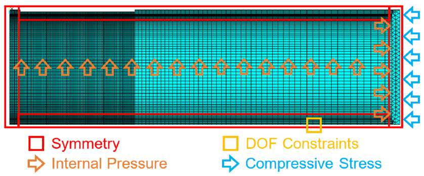
In this model, my aim here is to model interacting correded pipe subjected to internal pressure and axial compressive stress.
The mesh below has 34836 elements and 164338 nodes but element display shows
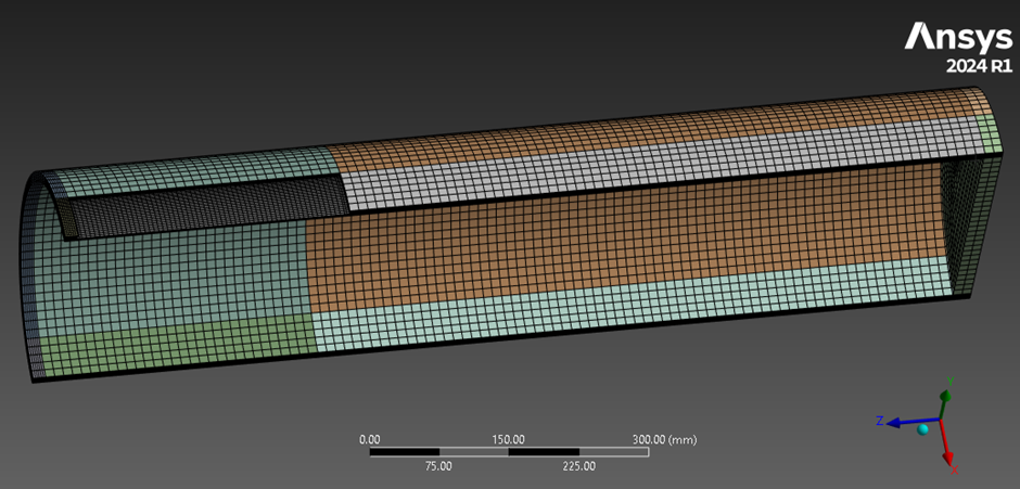
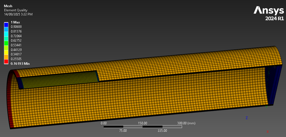
-
August 14, 2025 at 7:43 amSubscriber
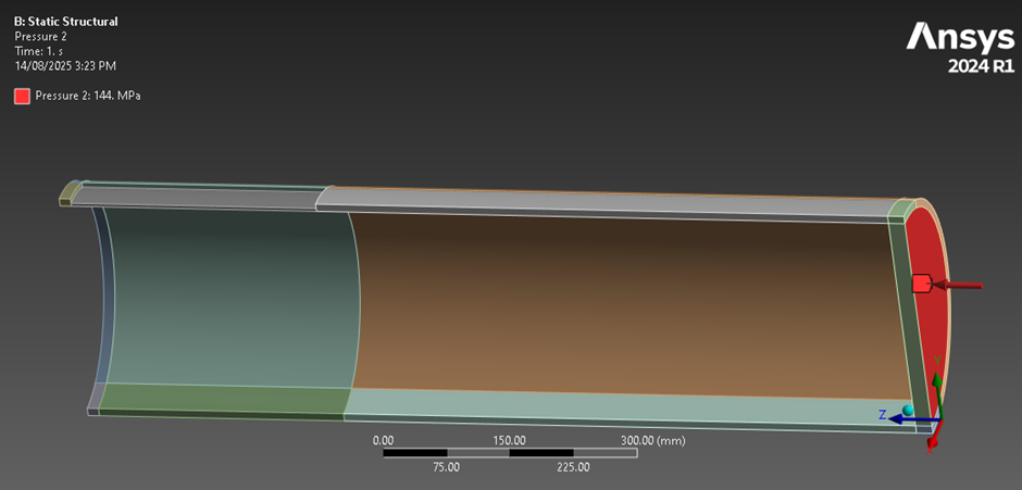
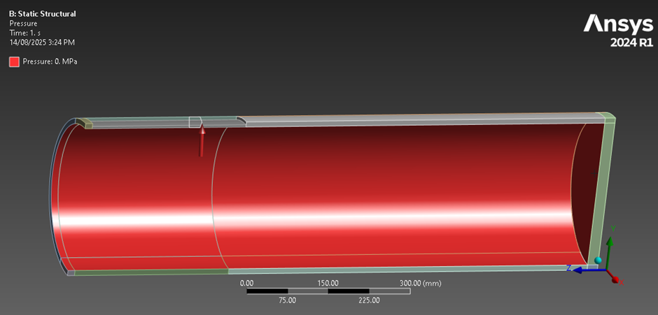
In applying the combined loads, under analysis setting, I used 2 number of steps, step 1 - axial compressive stress only, step 2 - introduction of internal pressure plus axial compressive stress. The degree of freedom is applied as below in yellow,constraine in x and y direction, the pipe material is mild steel, but the end cap is made of rigid body material- for even distribution of axial stress
the modeling failed with some messages"There could be possible overconstraint between the bonded contacts which use the MPC formulation, to identify those overconstraint regions use the Contact Trackers or the Status under the Contact Tool".
I don't know if the DOF, mesh or axial stress that caused the buckling
Sir please would like to know your advice
Kind regards
-
August 14, 2025 at 3:45 pmSubscriber
Since the buckling occurred in Step 1, it is due to the compressive axial load. You should plot the graph of total deformation versus time to see at what value the graph suddenly goes up. You should plot the last converged increment of load so you can easily calculate the last axial load value by multiplying the time value by the load magnitude.
When you say “end cap is made of rigid body material” do you mean under the Details for that solid, the Stiffness Behavior is set to Rigid, or do you mean that the material assigned has a much higher Young’s Modulus than mild steel but the Stiffness Behavior remains as Flexible?
Why introduce an artificial condition on the end-cap in the model? If the real end-cap is not rigid, making it so can alter the onset of buckling.
If you used the Share button in SpaceClaim, there is no need for any Bonded Contact. Is there in fact any Bonded Contact under the Connections folder?
What DOF constraint did you apply to the bottom side of the model? A point constraint is unrealistic. What are the real supports for this structure?
-
August 14, 2025 at 6:23 pmSubscriber
Good morning Sir,
The main pipe body has young modulus of 200GPa, the end cap which is the rigid body section,20mm thick has higher young modulus of 200000GPa, which is to allow for equal distribution of axial compressive stress.
At the bottom side of the pipe(yellow) DOF was applied using displacement, constrained in the x and y to prevent unwanted rigid body movement, but z direction allowed movement.
-
August 14, 2025 at 6:32 pmSubscriber
I made use of the shared button in the spaceclaim, model attached here in.
https://drive.google.com/file/d/1QjxxIcfibKXPlFdOQhhcXoC3OkdfPcng/view?usp=sharing
when the defected pipe is subjected to combination of axial compressive stress from the outer end cap and internal pressure, one can then predict failure pressure of the pipe, when ultimate tensile stress equals von mises equivalent stress.
-
August 14, 2025 at 6:42 pmSubscriber
the successful modeling of the pipe failure pressure may look like the diagram below, I have not found out how to get that
-
August 14, 2025 at 6:46 pmSubscriber
kind regards
-
August 14, 2025 at 8:49 pmSubscriber
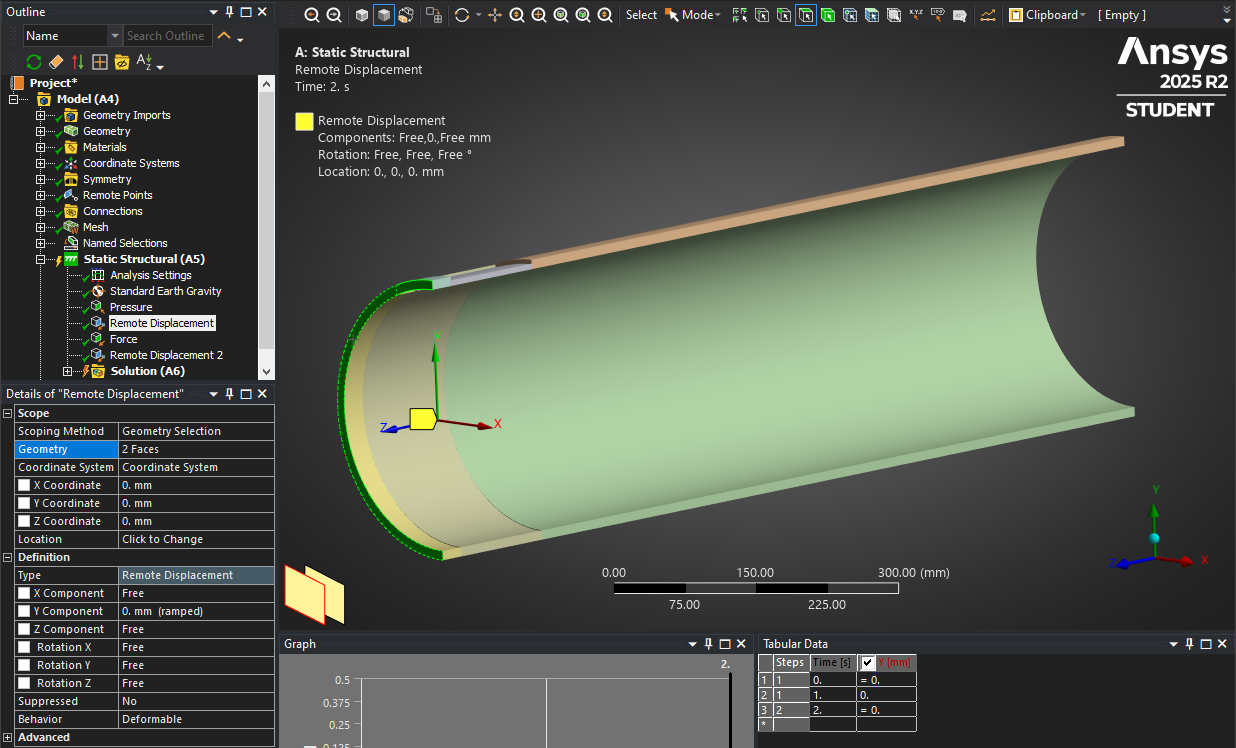
Displacement is a symmetry BC. The same geometry appears on the opposite side of this plane.
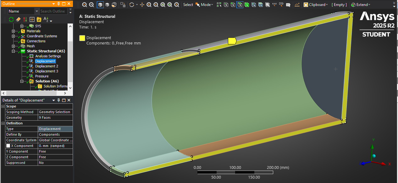
Displacement 2 is a symmetry BC. This means that if you reflect the model about this plane, you will get the same geometry on both sides of the plane.
How is it possible that you have the same defect in wall thickness on both sides of that plane with a narrow band of full wall thickness at the center?
It seems it would be more correct to slice the pipe half way along the length of the defect on the red line and apply the symmetry there. Do you agree?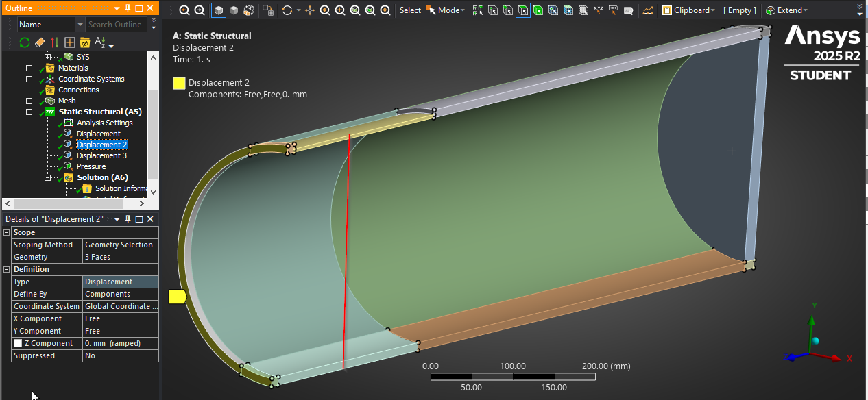
Displacement 3 is a single vertex that prevents the rigid body motion along the Y axis.
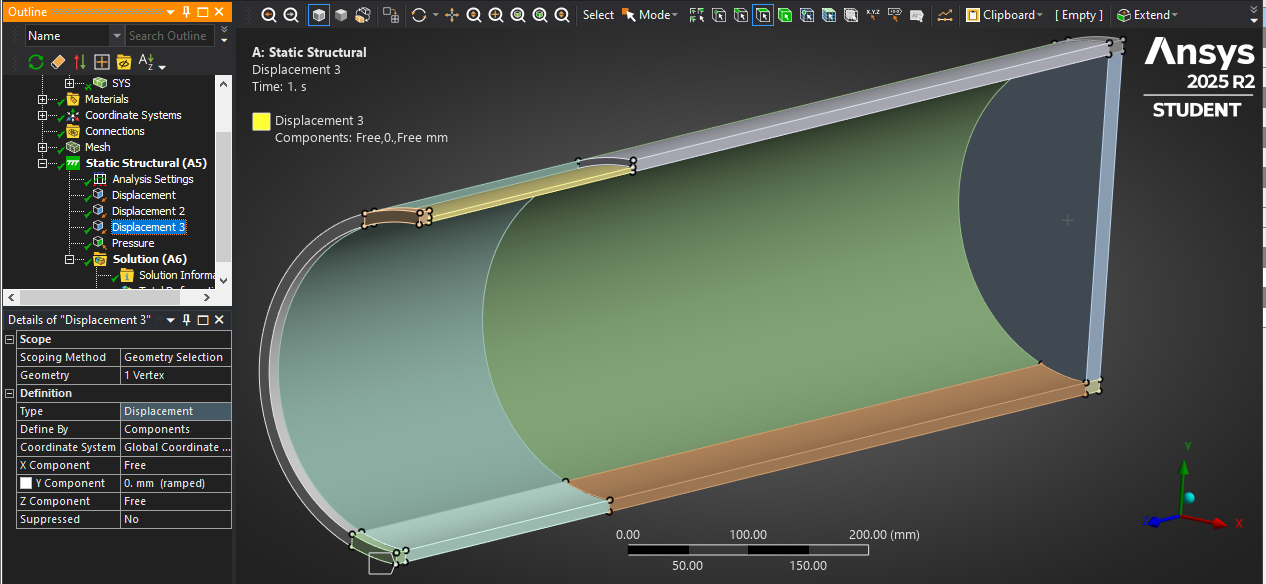
An alternative model would be to extend the pipe the same distance in the +Z direction and put an end cap on that end also.
-
August 16, 2025 at 2:41 amSubscriber
Good morning Sir,
Thank you kindly for your prompt reply. The longitudinally aligned interacting defects are in both sides of the plane, the symmetrical quarter pipe is made up of 300mm length defect and the narrow band of full wall thickness at the centre is (13.69mm long), but has the full defect space between the two alinged defects as(13.69x2 - 27.35mm long), hence the quarter pipe seems correct to me.
My task is to follow the modeling procedure of this journal paper attached here in, try reproducing it before introducing my own modifications.
https://drive.google.com/file/d/1L27wd3uBhSzW7GHmTWtVLtDFZVzqo6OJ/view?usp=sharing
Kind regards
-
August 16, 2025 at 3:32 pmSubscriber
Thank you for the paper. Now that I have read that, I understand the symmetry condition you applied correctly simulates two longitudinal defects.
This image from one of your models
suggests that the boundary conditions are not correct. I can check what you have. In Workbench, use File, Archive to create a .wbpz file and upload that to your Google drive and reply with a link.
-
August 16, 2025 at 4:14 pmSubscriber
Good morning Sir,
Please find attached here in the wbpz file. I attempted shifting the position of the DOF to be on the 20mm rigid body side, the buckling was not there again, but it is not yet correct.
https://drive.google.com/file/d/1nmy6-i6XzsqS5PZQI7g12FAynh5u-G4U/view?usp=sharing
-
August 16, 2025 at 9:35 pmSubscriber
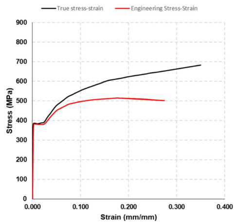
Looking at the Engineering Data, you have defined a Bilinear Isotropic Hardening plasticity model with a 360 MPa yield strength and a Tangent Modulus of 14500 MPa. The paper uses a Multilinear Hardening curve. You would get results closer to the paper if you digitized the true stress-strain curve and put it in that material model.
Looking at the no defect model I see a few problems.
- There is only one element through the thickness. You should change the mesh method to Sweep and select the inside face as Source so you can specify 3 elements through the thickness.
- At one end, you have a fixed support, at the other end, you have a symmetry condition. When the internal pressure load is applied, the Poisson's ratio causes an axial tensile stress in the pipe wall. Is that your intention?
- If I delete the Fixed Support and add a Y=0 constraint on one vertex, I get a very low state of axial stress.
- You should add a Cylindrical Coordinate System at the center of the pipe.
- The material has exceeded the yield stress and entered the plastic strain region of the material model.
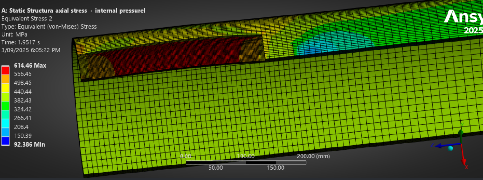
Looking at the axial stress + internal pressure model I see a few problems.
- There is no need to use an element face for the DOF-1 Displacement support. It doesn't survive remeshing. It is better to select a vertex.
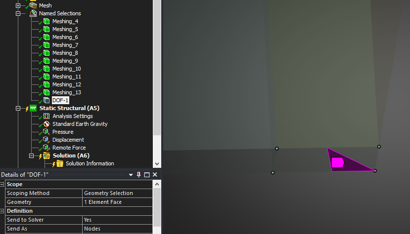
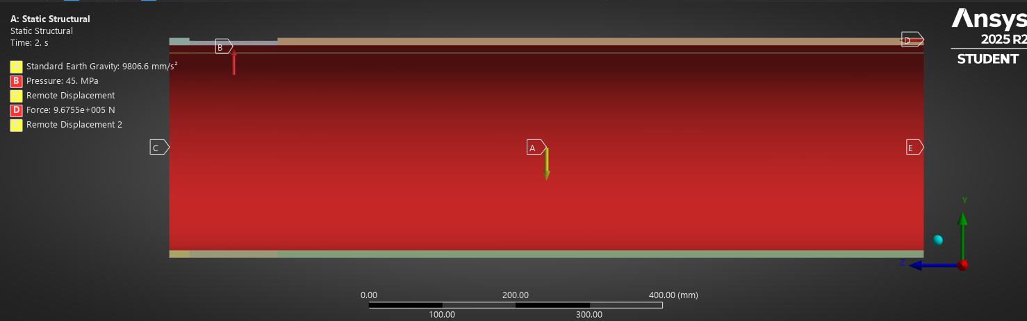
- The internal area of the end cap is 30788 mm^2, the pressure in step 2 is 24 MPa. That creates an axial tensile force of 7.39e+5 N but the Remote Force on the end cap only applies 6.56e+5 N therefore the net axial force is tensile, not compressive! If you suppress the Symmetry region for the Z direction and put a Displacement of Z = 0 boundary condition on those faces, you will find the Force Reaction at the end of step 2 is a slight tensile load of 0.88e+5 N or the difference between those two loads. Is this what you intended?
- In Ansys 2025 R2, the the PCG iterative solver is automatically selected by Program Control logic and solves in about 9 minutes on my laptop, but the Direct solver takes 8 minutes to solve. I changed from Program Controlled to Direct.
-
August 19, 2025 at 5:39 amSubscriber
Good afternoon Sir,
In this modeling, I want to find the failure pressure( when the equivalent stress Von mises will be equal to the true ultimate tensile strength) of the defected pipeline.
I have removed the DOF from point constraints at the symmetry face(as you advised) and placed it at the OD, outer diameter of the rigid circle. I made use of the name selection for this outer cylinderical surface of rigid ring, then inserted the displacement; ux=0,uy=0, uz=free (free axial movement).
I also left the rigid ring out, when scooping the inner pipe for internal pressure and for the equivalent stress-von mises plotting.
I have focused the remote force only on the (outer) annular face of the rigid ring. Please I will be attaching the current file for you to see and comment. The DOF error on the journal had made it very difficult for me to compare results with the journal.
-
August 19, 2025 at 11:39 am
-
August 20, 2025 at 4:16 pmSubscriber
Good morning Sir,
Please find attached here in my updated modeling for axial stress and internal pressure, I have made additional corrections, yet the model has not converged.
https://drive.google.com/file/d/1StfVs2oIkXQn3Zvp0niG0t3W1FE70_Ua/view?usp=sharing
-
August 20, 2025 at 8:14 pmSubscriber
You misunderstand how to identify the burst pressure in a nonlinear plasticity material model.
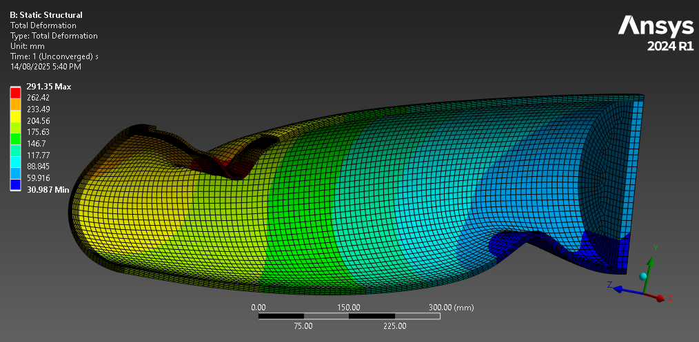
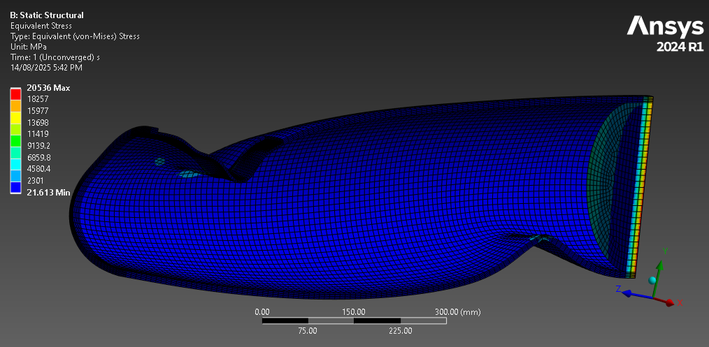
You do not want the model to converge. Ideally, you have a model that fails to converge after an exponential growth in displacement as the pressure is applied gradually.
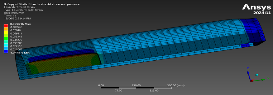
If you plot Pressure versus Maximum Total Deformation, you get exactly that. I have made a chart of that below. This is one way to define burst pressure.
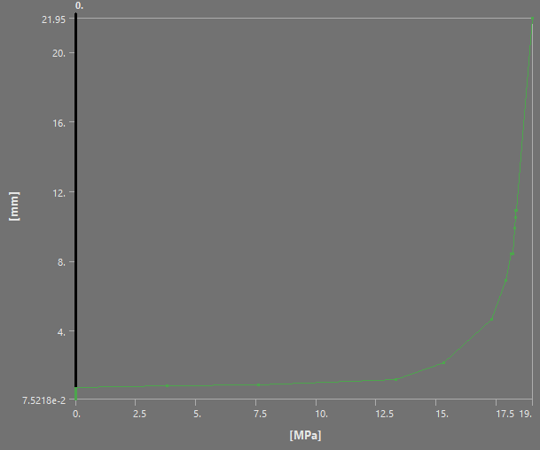
You must ignore the unconverged row in the Tabular data. The last converged row has a pressure of 18.321 MPa, which is the failure limit.
The paper you provided used a different definition of failure.
-
August 21, 2025 at 3:27 amSubscriber
Good morning Sir,
What I mean is that I am still trying to generate a clean result, I realised that the failure pressure is about 18.321 MPa. Something is still preventing me from getting a clean completed result.
Kind regards
-
August 21, 2025 at 11:24 amSubscriber
What do you mean by a clean completed result? Do you mean that the last load increment did not converge and created the messy unconverged plot at time step 2? If you want the analysis to end just before it does not converge, simply put in a pressure load of 18.3 MPa. However, that is unnecessary because you already have that result. It is the second last result in the tabulated data. What is preventing you from using that result?
Here is a video I made: https://www.youtube.com/watch?v=qMmEhZll0kI
You could choose to use the same definition of burst pressure as the paper used instead of the definition I explained above. From the paper:
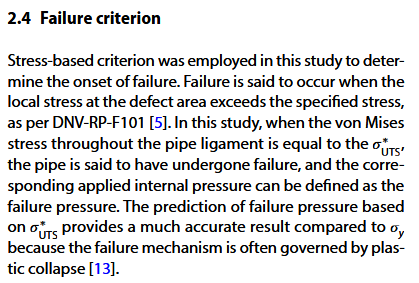
-
August 26, 2025 at 2:47 amSubscriber
Good afternoon Peter,
Thank you kindly for all your time to answer my questions. The video was helpful and you have already explained the issue I was asking. I was bent on getting the results as it was in the Journal paper.
Kind regards
Martin
-
August 30, 2025 at 9:14 pmSubscriber
Good morning Peter,
Thank you kindly for your time and interest in addressing my Ansys issues which has improved my modeling. Please I have attached here-in, Ansys 2025 file, an attempt to achieve failure pressure using combined internal pressure and axial compressive stress on corroded pipe. In the model, I placed the DOF on the outer diameter of the rigid ring, I think DOF on the YZ symmetry-face creates stress singularity. Please Sir, I would like your feedback and comment on the model and your possible updated Ansys attachment.
Thank you kindly
Martin
https://drive.google.com/file/d/1mNImfTgmr01tV_oV70E3Ik1fG50PkIZG/view?usp=sharing
-
August 30, 2025 at 9:44 pmSubscriber
Martin, the link you provided is to a pdf file of the paper, not an Ansys archive. Please reply with a corrected link.
Regards,
Peter
-
August 31, 2025 at 3:36 amSubscriber
Good afternoon Peter,
Please find the link attached here-in.
https://drive.google.com/file/d/183AgQGdZeO73wBU59bttM8ecm9fkLr_x/view?usp=sharing
Kind regards
Martin
-
September 1, 2025 at 1:23 amSubscriber
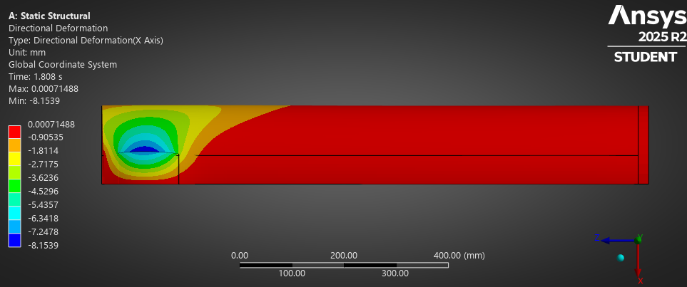
This model is missing an important constraint, the Symmetry region on the YZ plane (X axis) on the cut face at the centerplane of the pipe.
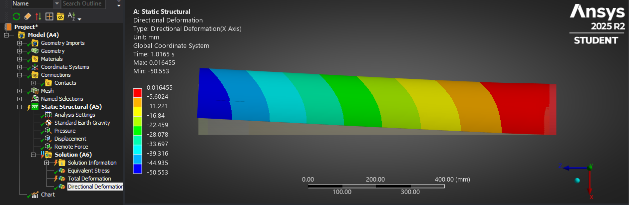
I cannot solve this model on the Student license because there are too many nodes to allow that (>128k) so you will have to add the symmetry region and solve the model again, but I was able to change the element order to Linear and that got the node count down and I could solve.
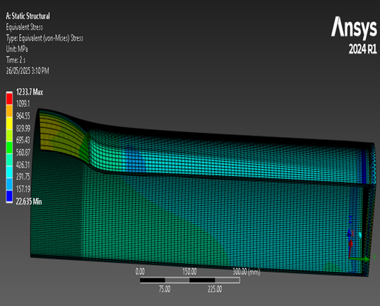
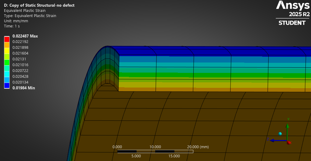
The model ran up to 80% of load step 2 and has a much smaller X deformation.
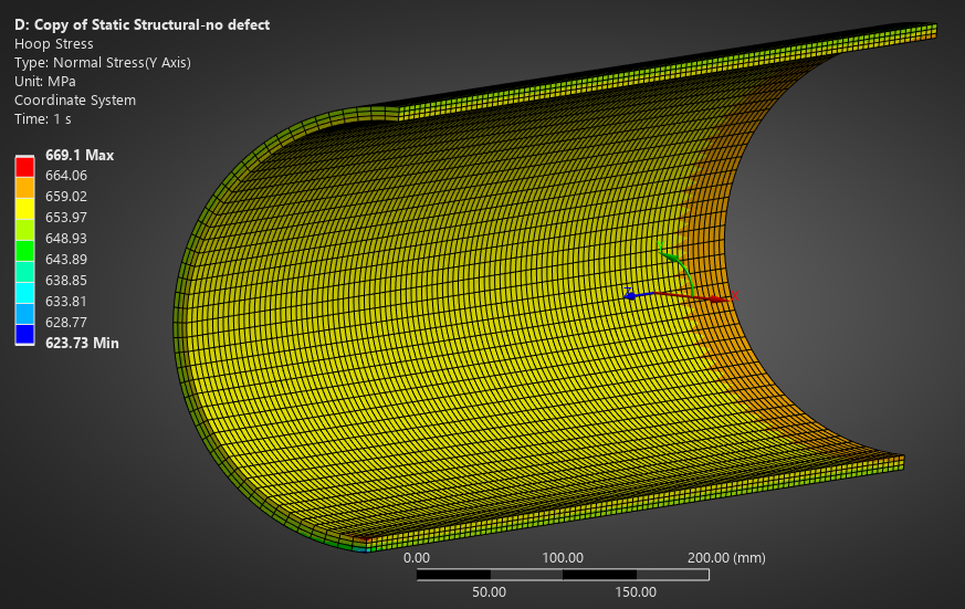
The directional deformation in the Y axis shows the defect region is beginning to burst.
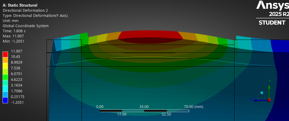
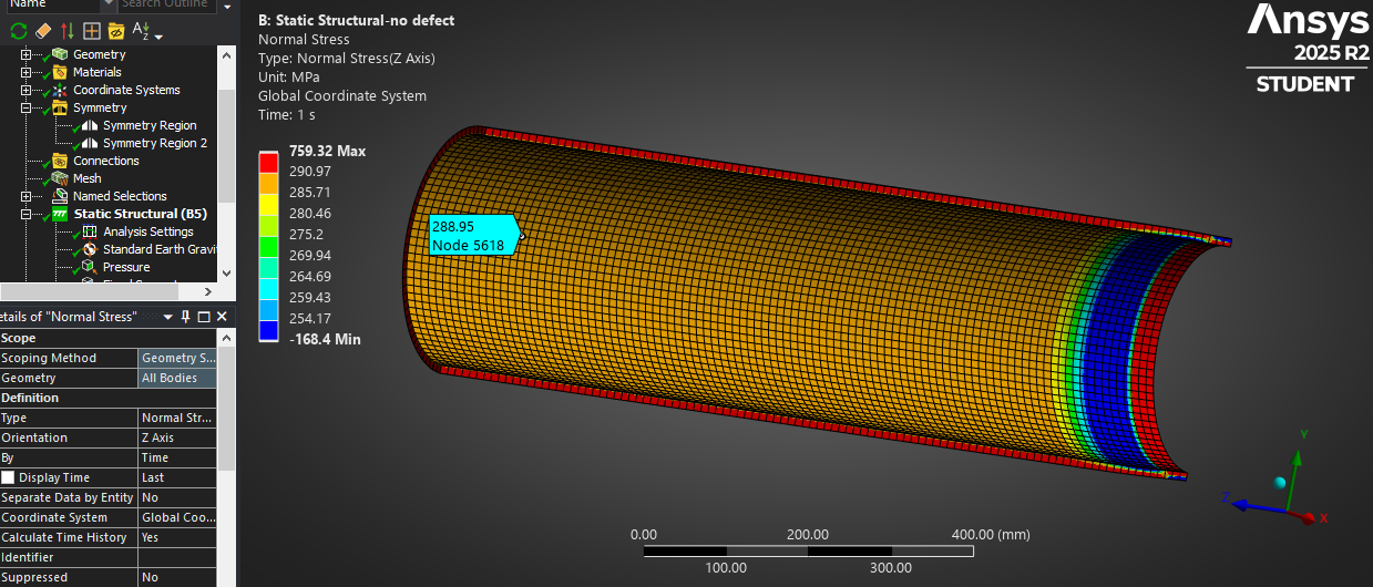
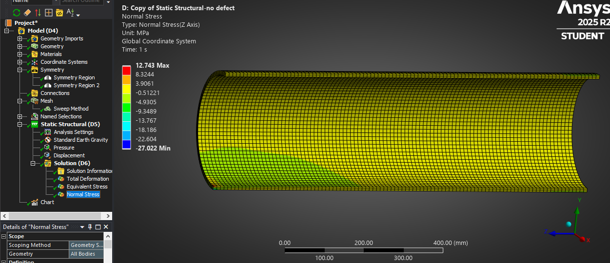
You will find the stress has gone down significantly with the Symmetry Region added.
-
September 1, 2025 at 5:00 amSubscriber
Good afternoon Peter,
Thank you kindly for pointing out that omission. Please I would like to have a copy of your model.
Kind regards
Martin
-
September 1, 2025 at 7:52 amSubscriber
Good evening Peter,
After putting the symmetry for XY and YZ, please I have attached the model was generated.
https://drive.google.com/file/d/1ryUsl6GIXGTa2S5bDYobRu_K4M-p3Ejl/view?usp=sharing
Kind regards
Martin
-
September 1, 2025 at 1:59 pmSubscriber
One mistake in your model is that the Displacement you put on the ring around the closed end is set to prevent motion in X, Y and Z, but you also have a Remote Force on the closed end in the Z direction, so all that force is supported by that Displacement BC and none of it goes into the pipe walls. Delete that Displacement BC.
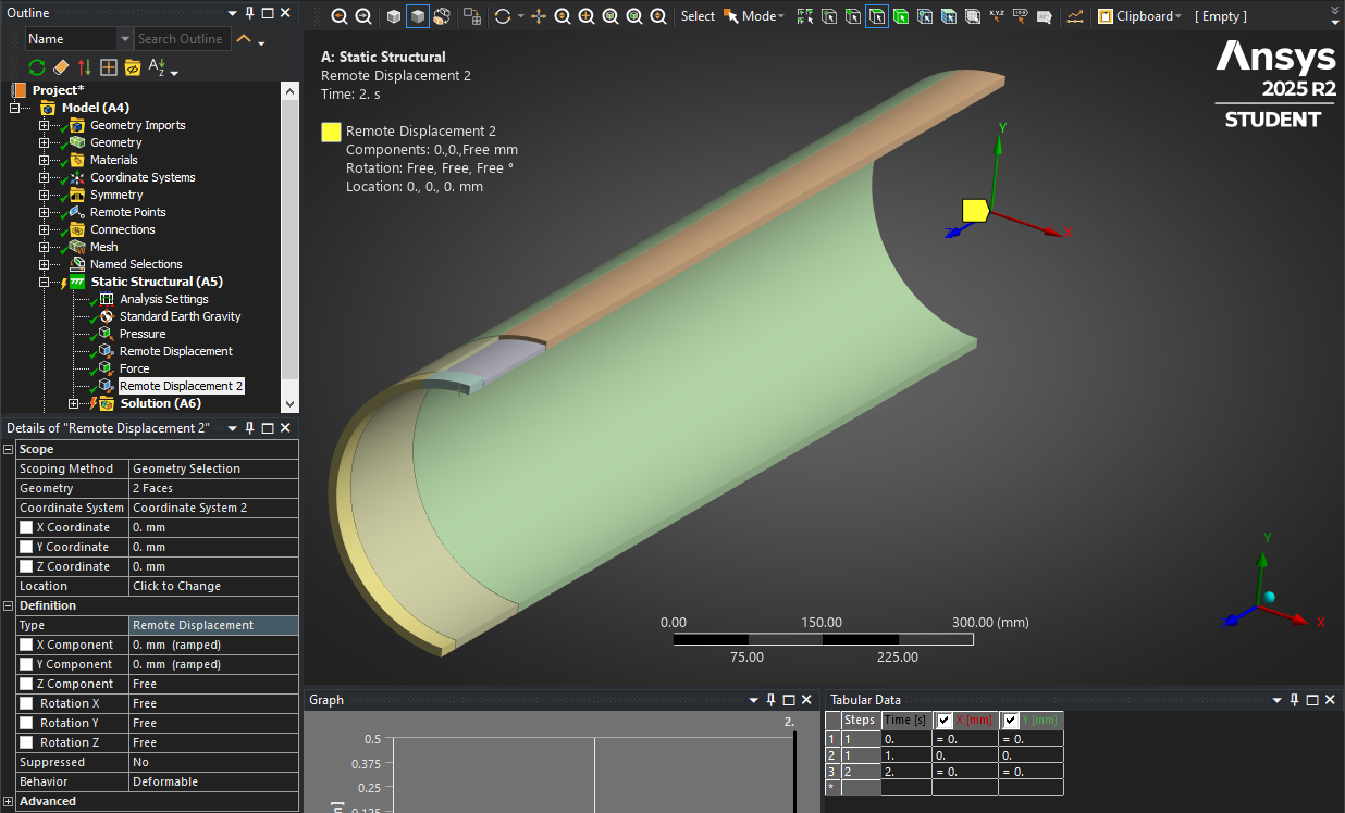
The two Symmetry Regions take away 5 rigid body DOF from the structure. Only Y displacement remains free. Therefore, the best constraint to remove that Y axis rigid body motion is a single vertex anywhere on either plane of the model. That vertex will have zero Y displacement. I suggest a Remote Displacement and select two vertices, one on the top of the pipe and one on the bottom of the pipe along the axis between the two symmetry planes and set Y=0. That way, the center of the pipe will be the fixed point.
-
September 1, 2025 at 4:31 pmSubscriber
Thank you kindly Sir.
-
September 3, 2025 at 8:04 amSubscriber
Good evening Peter,
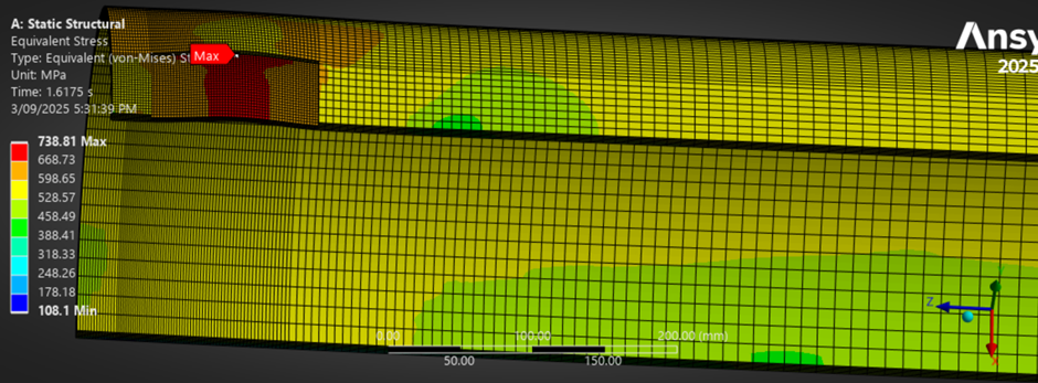
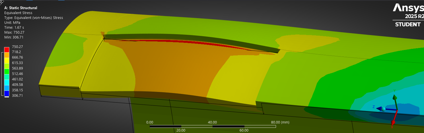
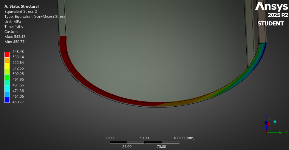
In this simulation attached here-in, I removed the DOF from the outer cylinder face of the ring and used remote displacement on two vertices at top and bottom, setting Y=0. The failure pressure gave about 27.5MPa (pressure when the equivalent von mises stress = ultimate tensile strength of 718.2MPa)
https://drive.google.com/file/d/1FjowjXEFoPgSijirLQ70UK1d7BCoKd5E/view?usp=sharing
Kind regards
Martin
-
September 3, 2025 at 8:06 amSubscriber
-
September 3, 2025 at 8:20 amSubscriber
In the second modeling below, DOF is at the outer cylinder face of the ring, using displacement with ux=0, uy=0, uz=free, the failure pressure here is about 21.5MPa.
-
September 3, 2025 at 8:22 amSubscriber
Here is the second modeling, https://drive.google.com/file/d/1qODcS9V6z24HJrLB1kuZTiVE6k5LElSb/view?usp=sharing
Kind regards
Martin
-
September 3, 2025 at 2:30 pmSubscriber
Different boundary conditions result in different burst pressures.
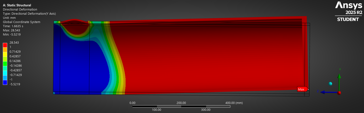
In the model with no Y constraint on the end cap, the end cap lifts up. Here is a true scale deformation plot of my linear order element model with the remote displacement on two vertices at the center plane.
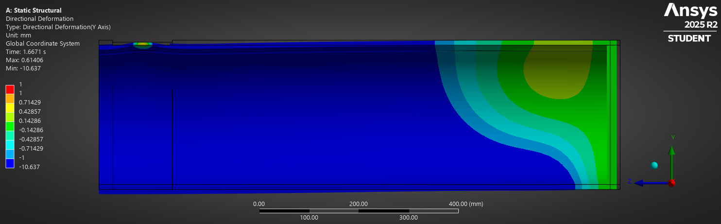
Here is the plot from the model with X=Y=0 displacement on the ring of the end cap. You can see the centerplane on the left end of the pipe moves down by 10.6 mm.
You must choose which boundary condition more accurately represents the real test conditions.
You might even choose to use both a Remote displacement of X=Y=0 on the cut face of the symmetry plane as well as a displacement on the cap end.
-
September 3, 2025 at 5:29 pmSubscriber
Good morning Sir,
Thank you for your prompt response always. One thing I want to point out is that the 20mm end cap rigid ring(which has much higher young modulus than the pipe body 200000GPa) because of its ultra stiffness, I do not include it when solving the maximum equivalent von mises stress value ( I include only the pipe body which has young modulus of 200000MPa) because it dominates the stress values, affecting the result. The rigid 20mm section is basically to help distribute axial compressive stress evenly( through the annular end of the pipe)
-
September 3, 2025 at 5:35 pmSubscriber
I observed that when I stopped including the rigid ring in solving the max equivalent von mises stress, the result looked better.
Kind regards
Martin
-
September 3, 2025 at 9:54 pmSubscriber
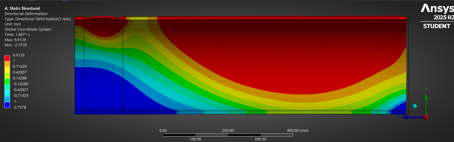
Yes, I agree the model is better without the end cap. The image below keeps the centerpoint of both ends of the pipe at Y=0 using Remote Displacements.
-
September 4, 2025 at 1:55 amSubscriber
Good afternoon Peter,
Thank you for the reply and the attached images. It appears no vertex was used here, DOF placed at a node at the center point of both ends of the pipe using remote displacement (Y=0), please can you throw more light.
I include the rigid 20mm to help distribute axial compressive stress evenly, but I do not include it during solving for the stress. I apply internal pressure at the pipe internal wetted faces only,excluding the rigid ring. I also try to avoid stacked boundary condition, that is, keeping only one boundary condition at a face, like remote force staying at the flat annular end face e.t.c, please what do you think.
Kind regards
Martin
-
September 4, 2025 at 3:57 pmSubscriber
A coordinate system was created at each end of the pipe on the pipe axis.
A remote displacement using the cut end faces had Y=0 defined for the pilot node at the center. Notice that behavior is Deformable. That means the average displacement of all the nodes on those faces has Y=0. The same faces are used in the Symmetry Region had Z = 0 defined on every node, and this is not in conflict with the remote displacement. During the solution, no warning were issued about overconstraint.
Another Remote Displacement is at the other end. I set both X and Y = 0 but I think the Symmetry Region along the center plane that keeps X=0 on every node is sufficient and the X=0 in the Remote Displacement is unnecessary. Since Z is Free, a Force can be applied to the end face.
When a Force is applied to a planar face, the solver automatically calculates a nodal force that evenly distributes the total force.
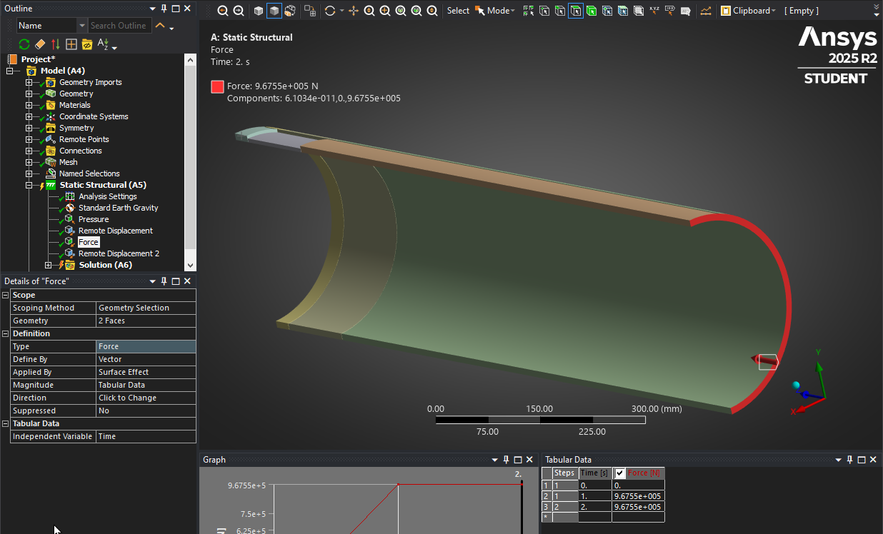
You say you want the axial compressive stress distributed evenly. Why stress? Why not force? The result of applying the force evenly is that the Z deformation is not equal over the planar cut faces. The plot below is at an internal pressure of 30 MPa (0.67*45).
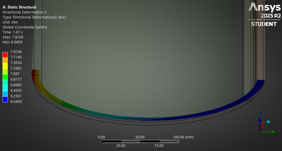
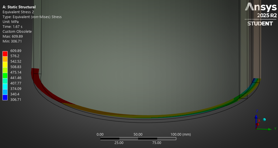
Since deformation is 6 mm on the +Y (defect) side of the end faces, while it is nearly 8 mm on the -Y side of the end faces. There is some average tilt of the faces and the faces do not remain planar. This causes higher stress on one side than the other (internal pressure = 30 MPa)
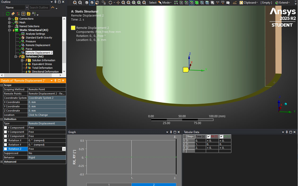
If you want even stress over those end faces, then you want this end face to remain planar and normal to the Z axis, but you want the nodes to be free to move radially in response to the pressure and applied force. To achieve this, you can promote the Remote Displacement to a Remote Point. Edit the Remote Point and change the behavoir to Rigid and use the Manual DOF Selection so only the Z component is Active.
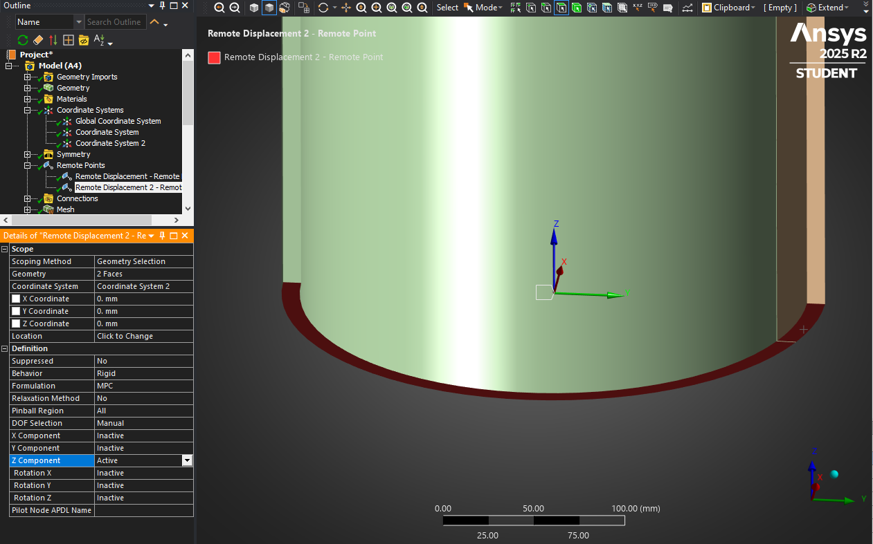
Edit the Remote Displacement to prevent rotation about the X and Y directions.
Now the end faces remain perfectly planar and normal to the Z axis (internal pressure = 27 MPa).
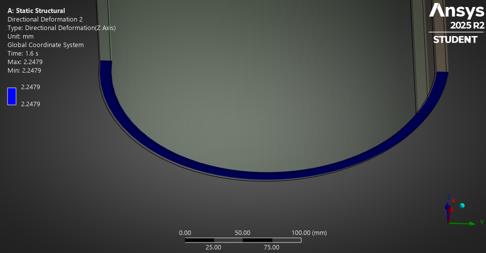
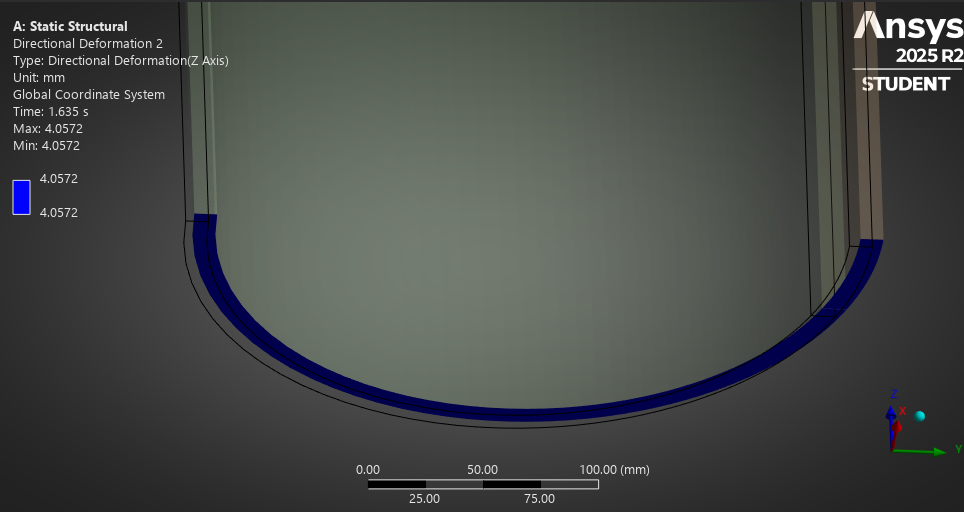
As the pressure increases from 27 MPa to 28.6 MPa, since there was no constraint on the Y displacement, we visually see the faces have more deformation in the +Y direction as well as the contour showing motion along the Z direction increases (the pipe is getting shorter as the pressure goes up).
The stress on the end faces have about a 100 MPa range for an applied pressure of 0.6*45 = 27 MPa.
You could add Y = 0 to the DOF of the Remote Displacement on the end faces and see what that solution looks like.
Another topic to explore is the exact definition of burst pressure. How do you define it? Is it the time at which any element exceeds the stress of 781.2 MPa? The problem with that defintion is it is mesh dependent. Use larger elements and you may get a higher burst pressure, use smaller elements and you may get a lower burst pressure. This is because there is a stress singularity at the sharp interior corner where the peak stress is found.
-
November 24, 2025 at 5:37 pm
mistralracingteam
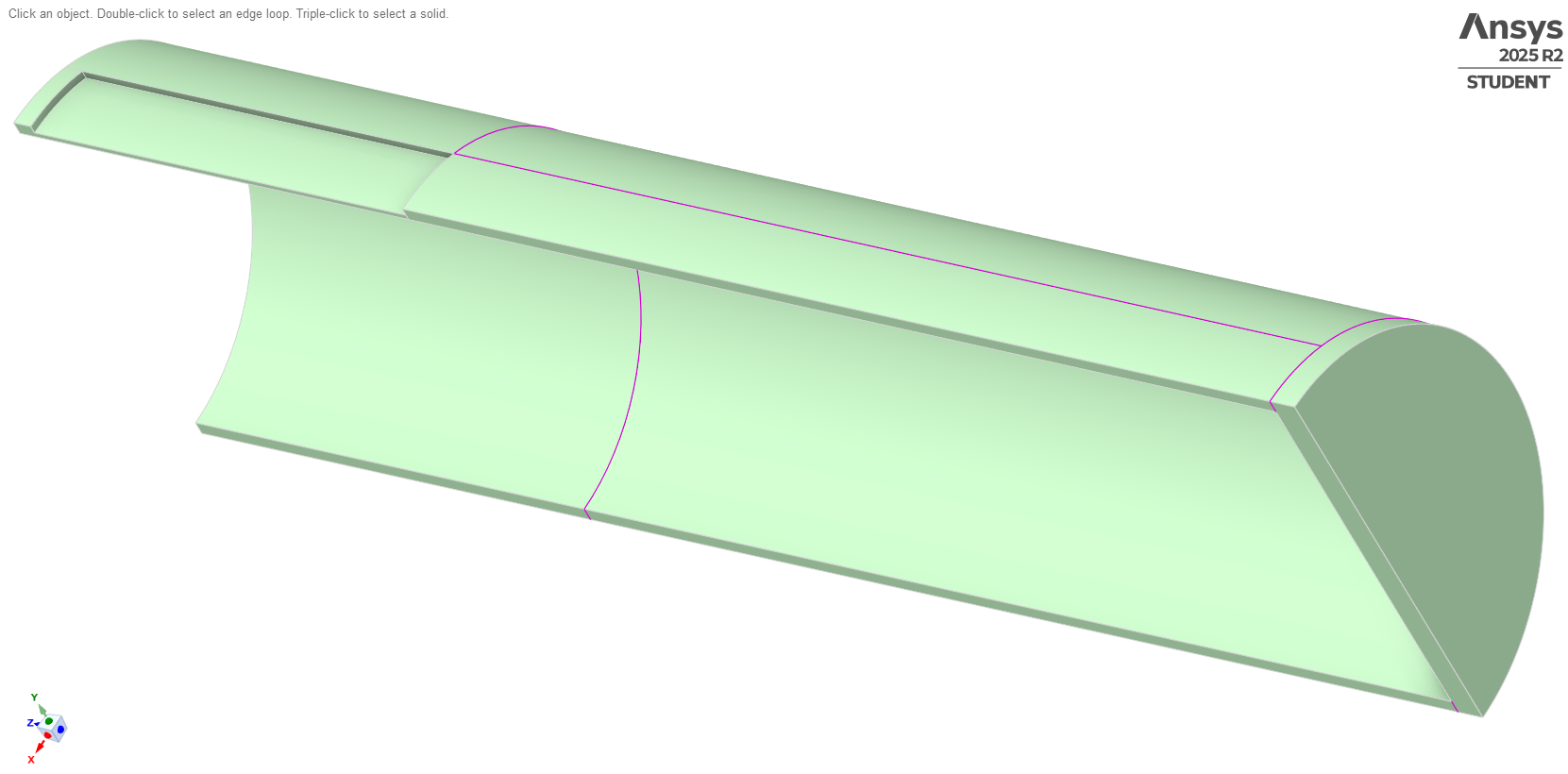
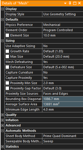
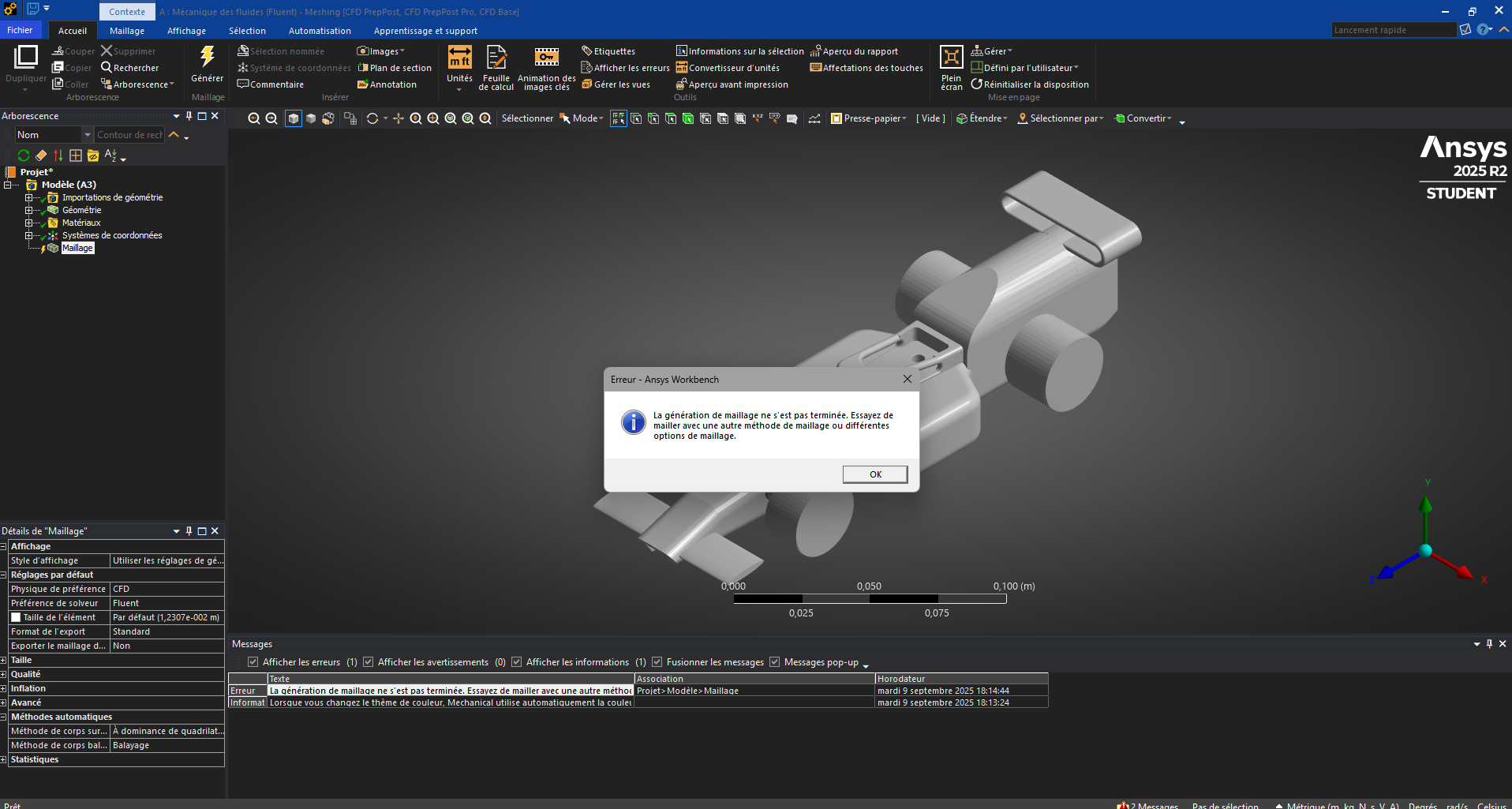
SubscriberHello, I need help testing the aerodynamics of this 3D model. The problem is that I get an error message when trying to create a mesh. -
November 24, 2025 at 5:38 pmSubscriber
-
November 24, 2025 at 6:01 pmSubscriber
mistralracingteam,
Please start a New Discussion in the Preprocessing channel.
-
- The topic ‘Help to solve the challenge of hexhedral meshing of inner edges with fillet.’ is closed to new replies.


-
peteroznewman
 5579
5579 -
scabo
 1885
1885 -
Dennis Chen
 1403
1403 -
javat33489
 1298
1298 -
Shyam Prasad V Atri
1021


© 2026 Copyright ANSYS, Inc. All rights reserved.
