-
-
March 26, 2026 at 1:45 pm
rihen.laifi.doc
SubscriberRecently, I am learning to simulate the graphene-based antenna using HFSS software. There are some issues I did not figure out.
According to my understanding, since there is no graphene material defined in the HFSS software, we need to define the material ourselves in the HFSS software. From the Kubo formula or Drude model, the complex conductivity of the graphene can be calculated, which is frequency dependent. However, in HFSS, the properties to define material only allows real values .Â
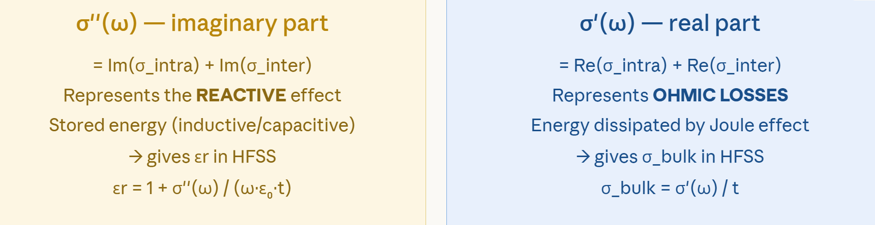
Is what is shown in this image correct/accurate?
Â
-
March 27, 2026 at 12:23 am
Takeshi Itadani
Ansys EmployeeIn HFSS, the complex permittivity is defined by two factors: Relative Permittivity and Dielectric Loss Tangent. The Dielectric Loss Tangent is the ratio of the real and imaginary parts of the complex permittivity.ÂOn the other hand, it is known that Bulk Conductivity and Dielectric Loss Tangent are equivalent, and traditionally, HFSS uses a method of setting the frequency dependence on Bulk Conductivity when setting frequency-dependent materials.ÂThe equations for Relative Permittivity and Bulk Conductivity that you have pasted are thought to demonstrate how to set the complex conductivity in HFSS using the above relationship.
-
Viewing 1 reply thread
- You must be logged in to reply to this topic.
Innovation Space
Trending discussions
Top Contributors
-
5834
-
1906
-
1420
-
1305
-
1021
Top Rated Tags
© 2026 Copyright ANSYS, Inc. All rights reserved.
Ansys does not support the usage of unauthorized Ansys software. Please visit www.ansys.com to obtain an official distribution.
