We’re putting the final touches on our new badges platform. Badge issuance remains temporarily paused, but all completions are being recorded and will be fulfilled once the platform is live. Thank you for your patience.
Fluids

Fluids

Topics related to Fluent, CFX, Turbogrid and more.

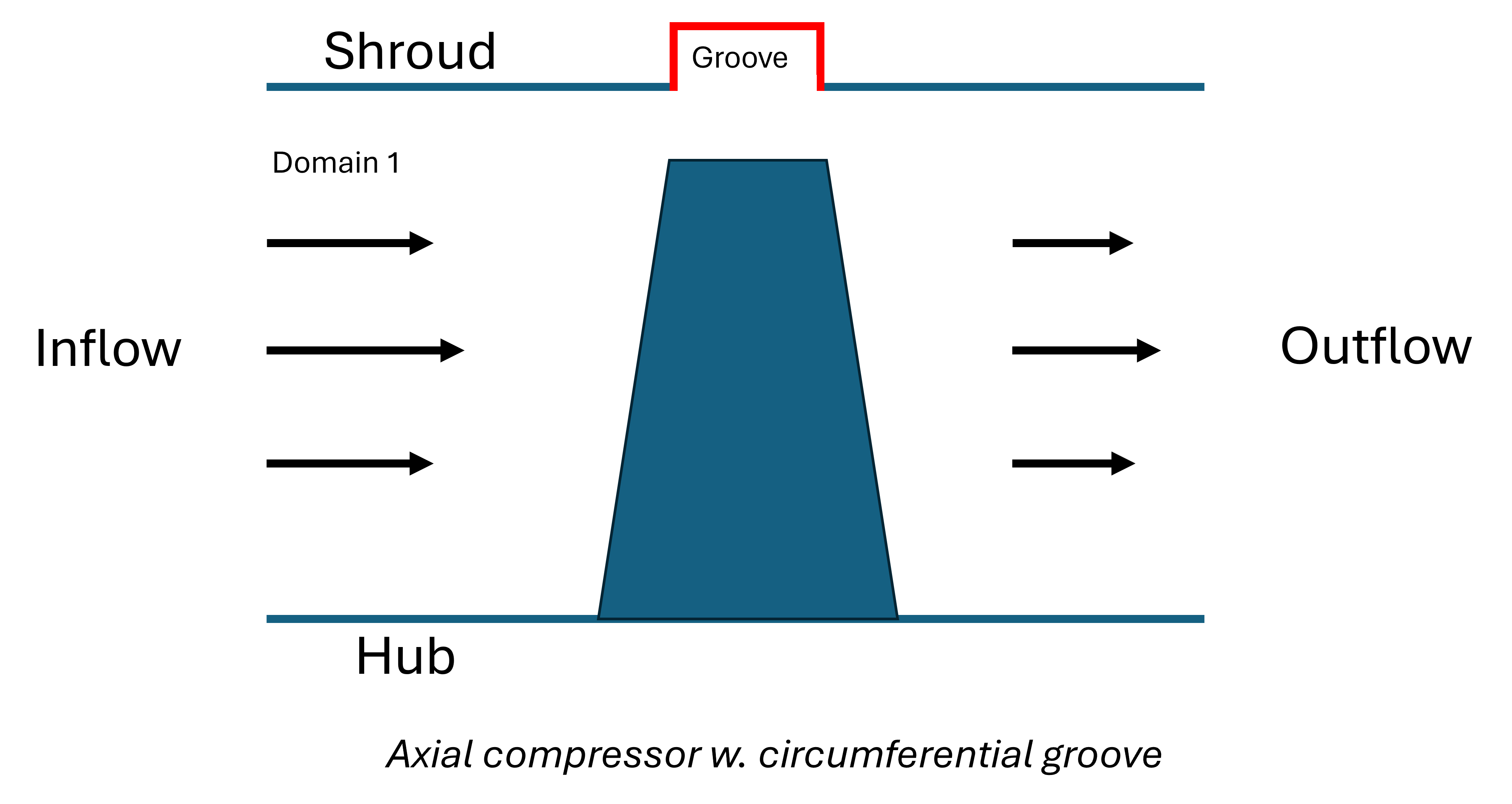
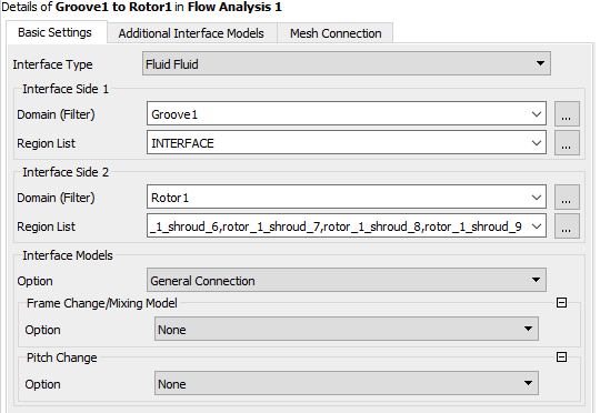
General connection between main flow path and circumeferential groove in CFX

    • zahlenritter
      Subscriber

      Dear community,

      I am trying to simulate an axial compressor with a circumferential groove, but the interface 
      between main flow path and groove is not working as expected and just generates a solid wall there.

      To simulate the influence of circumferential grooves I am given a mesh of an axial compressor.
      In a CAD-Software I construct my groove, which I importat and mesh in ICEM. Finally I load the 
      mesh as a .cfx5-file into my case. I create a domain interface between compressor shroud and the groove
      side, pointing towards the shroud. For non-overlapping part at the compressor I apply a no slip wall as a a nonoverlap
      Condition. 


      During postprocessing I noticed that the interface between both meshes is treated as a wall and not an interface with momentum exchange.
      I suspect that small geometric differences which are not visible, cause the meshes to not exactly match in the radial direction. As a result
      the no slip conditions is applied at the whole shroud.

      But how do I fix this problem?

      Best regards


    • CFD_Friend
      Ansys Employee

      Hi,

      The reason is that the distance between the interface faces is above the tolerance level. You have to keep both of them very close to achieve a proper connection. Otherwise, it creates a non-overlap condition. Try to make this as close as possible to avoid such problems.

      You can check whether the interfaces are in non-overlap condition or not, using contours in CFD-Post. Select the shroud boundary, and create a contour using the variable "Nonoverlap Fraction"

      If the boundaries overlap, that section will be colored blue (value =  0), if there is no overlap, then that region will be colored red (value =1)

Viewing 1 reply thread
  • You must be logged in to reply to this topic.