-
-
April 17, 2021 at 10:50 am
Costas
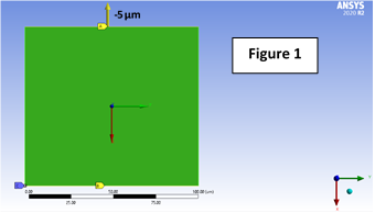
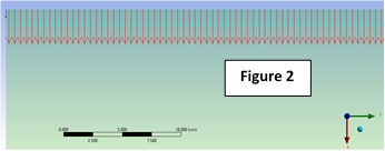
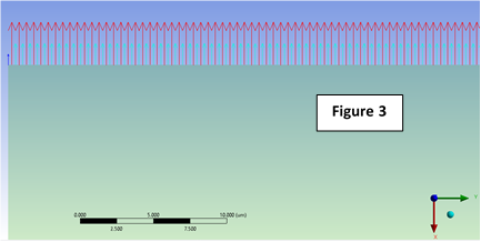
SubscriberHello.nI am a new ANSYS user and I am trying to make a simple model for uniaxial tension (please see Figure 1). The analysis is 2D plane strain. The boundary conditions are: a) bottom edge null displacement in the x-axis and free in the y-axis, b) left bottom vertex fixed, c) top edge free in the y-axis and -5 micrometers displacement.nI use program-controlled elements which turned out to be (as I found in the solution information) PLANE183 (quadrilateral with 8 nodes). I use ANSYS 2020 R2.nSo, I probed a reaction force on the top edge and then I used user-defined results (ENFOVECTORS and FVECTORS) to get the force at each node. As expected, the sum of each nodal force gives the total reaction force given by the probe.nMy questions are:n1. What is the difference between ENFOVECTORS and FVECTORS?n2. Do the red arrows represent the force at the corner nodes whereas the green arrows represent the force at the middle nodes (please see figures 2 and 3)?n3. Why the ENFOVECTORS give forces in the positive x-axis direction whereas FVECTORS give forces in the negative x-axis direction (both give the same absolute value in force)? Please see Figure 2 and Figure 3n4. What is this small force vector on the top left vertex (the same appears on the top right)? Please see Figures 2 and 3n5. Why when the results of ENFOVECTORS and FVECTORS are shown, the mesh cannot be shown? Please see Figures 2 and 3nThank youn

 nn
nn
-
April 19, 2021 at 9:19 am
1shan
Ansys EmployeenENFOVECTOR - Element nodal force vector, FVECTOR - Nodal force vectors. Element nodal means element data reported for each element at its nodes. Element nodal data consist of the element derived data (such as strains, stresses, fluxes, and gradients) evaluated at each of the element's nodes. These data are usually calculated at the interior integration points and then extrapolated to the nodes. Whereas the nodal solution from an analysis consists of the degree-of-freedom solution, such as nodal displacements, temperatures, and pressures. For vector degrees of freedom and corresponding reactions. nAnd yes, the red arrows represent the force at the corner nodes whereas the green arrows represent the force at the middle nodes. I am not sure about the corner nodes though.nRegards,nIshan.nn -
April 19, 2021 at 7:06 pm
Costas
SubscriberMany thanks Ishan.nIs there a way to check the elemental coordinate system during the construction of the model?nRegards,nCostasn -
April 19, 2021 at 11:17 pm
BenjaminStarling
SubscriberThe opposite direction of the forces is not caused by the difference in coordinate systems. APDL and Mechanical take care of the directions when requesting results. You can specify any arbitrary coordinate system for the elements and you will get the same result. nThe reason they are opposite is because the ENFO result is representative of internal force, you can plot ENFOVECTORS scoped to the whole body, and see the internal force at each element, including the discontinuity between elements. FVECTORS is representative of applied external forces, when scoping FVECTORS to a body, there is no result through the domain, only at locations where boundary conditions are applied. Internal force and externally applied forces are equal and opposite by definition, although FEM does not guarantee that they are exactly equal in magnitude.nQuadratic elements can have differing stiffness at the corner and midside nodes. Because you applied a displacement constraint this results in the two different magnitudes at corner and midside nodes. If you apply a force boundary condition, you should see a similar F result at both, with slightly different displacements. The most interesting example of this is quadratic solid elements, which have negative stiffness at their corner nodes.n -
April 20, 2021 at 4:18 am
1shan
Ansys Employee,nThank you for correcting!!! I'll change my answer. Any idea why the plate corner nodes have less stiffness? Is it because they are being shared by only one element ?nRegards,nIshan.n -
April 20, 2021 at 4:51 pm
Costas
SubscriberThanks a lot.nVeru helpful clarification!nRegards,nCostasn
-
Viewing 5 reply threads
- The topic ‘FVECTORS and ENFOVECTORS in ANSYS Mechanical’ is closed to new replies.
Ansys Innovation Space


Trending discussions


- The legend values are not changing.
- LPBF Simulation of dissimilar materials in ANSYS mechanical (Thermal Transient)
- Convergence error in modal analysis
- APDL, memory, solid
- How to model a bimodular material in Mechanical
- Meaning of the error
- Simulate a fan on the end of shaft
- Nonlinear load cases combinations
- Real Life Example of a non-symmetric eigenvalue problem
- How can the results of Pressures and Motions for all elements be obtained?
Top Contributors


-
3882
-
1414
-
1241
-
1118
-
1015
Top Rated Tags


© 2025 Copyright ANSYS, Inc. All rights reserved.
Ansys does not support the usage of unauthorized Ansys software. Please visit www.ansys.com to obtain an official distribution.


