-
-
January 25, 2025 at 5:48 pm
berryd
Subscriberhi, I have these two parts (1: Contact Body, 2: Target Body), with frictional contact between them. Partial view is shown below.
At the moment, I am able to simulate in transient ansys such that they 'adjust to touch'. Can I seek advise on how to simulate assuming part 1 penetrates/interferes with part 2 by 5-10 um.Â
I tried to apply -5 um offset under interface treatment of frictional contact ( offset only, no ramping option). However, the contact status shows a gap instead of penetration as shown below.Â
Thanks for your help.
-
January 25, 2025 at 7:14 pm
peteroznewman
SubscriberInstead of -5 um of offset which opened up the gap, try using +5 um of offset to cause some interference.
-
January 26, 2025 at 2:49 pm
-
January 26, 2025 at 3:22 pm
peteroznewman
SubscriberThe solver only cares about Penetrations and Gaps which are measured using nodes and elements. Don't pay attention to Geometric Gap values. Add a Contact Tool to the Solution branch and measure the Pressure, Penetration and Gap with that tool. When there is an actual gap, it is reported with a negative sign. I don't know why the developers used this sign convention, just be aware that it is the opposite of what most people expect.
-
January 27, 2025 at 1:51 am
berryd
SubscriberÂ
Peter, I see.
The penetration measured from solution branch is max 0.1123 um only though, that too at the end of load step. Shouldn’t it be 4.9748 um, that too at the beginning of load step, since the contact status (from initial information) shows that.Â
Even the solver information shows below msg
-
January 27, 2025 at 2:27 am
peteroznewman
Subscriber
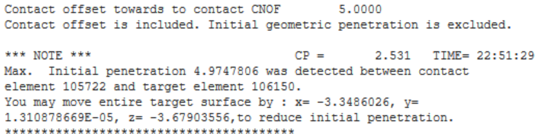
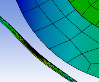
The initial contact status reports the penetration that exists before the solver starts to search for equilibrium of the forces on the node and elements with closed contact contact status. The solver performs iterations, moving nodes around until it converges on equilibrium. Then it writes that converged substep into the result file. During convergence iterations, the penetration is going to be driven down to a very small value by defoming the material on either side of the contact pair. Ideally, there is zero penetration when convergence has been achieved. One contact formulation (Pure Lagrange) delivers zero penetration but the other contact formulations leaves a tiny amount of penetration which can be adjusted by editing the Normal Stiffness of the contact.
For surface-to-surface contact elements, the program offers several different contact algorithms (formulations):
Penalty method (KEYOPT(2) = 1)
Augmented Lagrangian (default) (KEYOPT(2) = 0)
Lagrange multiplier on contact normal and penalty on tangent (KEYOPT(2) = 3)
Pure Lagrange multiplier on contact normal and tangent (KEYOPT(2) = 4)
The penalty method uses a contact spring to establish a relationship between the two contact surfaces. The spring stiffness is called the contact stiffness. This method uses the following real constants: FKN and FKT for all values of KEYOPT(10), plus FTOLN and SLTO if KEYOPT(10) = 0 or 2.
The augmented Lagrangian method (which is the default) is an iterative series of penalty methods. The contact tractions (pressure and frictional stresses) are augmented during equilibrium iterations so that the final penetration is smaller than the allowable tolerance (FTOLN). Compared to the penalty method, the augmented Lagrangian method usually leads to better conditioning and is less sensitive to the magnitude of the contact stiffness. However, in some analyses, the augmented Lagrangian method may require additional iterations, especially if the deformed mesh becomes too distorted.
The pure Lagrange multiplier method enforces zero penetration when contact is closed and "zero slip" when sticking contact occurs. The pure Lagrange multiplier method does not require contact stiffness, FKN and FKT. Instead it requires chattering control parameters, FTOLN and TNOP. This method adds contact traction to the model as additional degrees of freedom and requires additional iterations to stabilize contact conditions. It often increases the computational cost compared to the augmented Lagrangian method.
An alternative algorithm is the Lagrange multiplier method applied on the contact normal and the penalty method (tangential contact stiffness) on the frictional plane. This method enforces zero penetration and allows a small amount of slip for the sticking contact condition. It requires chattering control parameters, FTOLN and TNOP, as well as the maximum allowable elastic slip parameter SLTO.
-
January 27, 2025 at 2:36 am
berryd
SubscriberSo if the solver is driving close to zero penetration during convergence, any way i can simulate the real condition where the body 1 is penetrating/preloading into body 2 by 5-10 um? The solver uses augmented lagrange formulation here for the frictional contact.
-
-
January 27, 2025 at 3:09 am
peteroznewman
SubscriberPerhaps you are confusing penetration with interference. For example, a plate has a 10 mm diameter hole in the center and there is a 10.02 mm diameter pin that you want to put in that hole. We say there is a 0.01 mm radial interference between the pin and the hole before the parts are assembled. This is the penetration that would be reported in the Initial Contact Status before the solver starts.
Let’s heat up the plate until the free expansion causes the hole to grow to 10.03 mm in size. Slip the room temperature pin in that hole in the hot plate and let it cool down. As the plate cools, the hole gets smaller until the hole makes contact with the pin. The surface of the pin doesn’t penetrate the hole, contact forces compress the pin and stretch the hole. When the assembly has returned to room temperature, the diameter of the pin inside the hole is now 10.01 mm and the diameter of the hole is also 10.01 mm. This is how the pre-assembly interference was resolved to a zero penetration assembled state.Â
This is the behavior that the contact algoritm simulates. You can have two parts sitting in CAD with an initial interference, but when the solver has finished, there should be zero penetration. This is the real condition.
-
January 29, 2025 at 10:52 am
berryd
SubscriberAh understand thnks. So, just to clarify here that although the penetration is an initial condition for contact, but the behavior would be similar to a constant preload being applied in assembly between two parts. Is that right?
Also, i simulated with 10 um offset, the visual for deformation exhibits a gap at 0.5x scale as you may see below. The gap for contact status under solution doesn't show any gap too. Any way to rectify this?
-
January 29, 2025 at 12:04 pm
peteroznewman
SubscriberThe contact algorithm resolves an initial penetration detected in the initial state of the parts to drive it practically to zero when the offset value is set to 0.
Contact elements are skinned over the structural elements at the surface of the parts. Offset is used to move the contact elements on one side of the contact pair away from the structural elements. You entered a 10 um offset, so that is where the contact elements are placed and where the penetration is driven to zero and you see the 10 um gap between the structural elements that you requested by moving the contact elements out by 10 um. If you leave offset at 0 then you won't see a gap.
A use case that makes sense for using an offset value is in the example of the pin in the hole. Let's say that in CAD, the pin and hole solid bodies are both drawn at a 10 mm diameter. Rather than editing the diameter of the pin to be 10.02 mm before bringing it in to mesh, just bring them in with no geometric interference, create the contact pair and type in the radial offset of 0.01 mm and the contact algorithm will compress the pin and stretch the hole and you will see a 0.01 mm gap between the pin surface and the hole surface. The stress in the parts will be almost the same as if you had edited the pin diameter in the CAD system to be 10.02 mm.Â
-
January 29, 2025 at 4:11 pm
berryd
SubscriberYes true, the case of pin in hole makes sense. I am still trying to evaluate if this offset treatment would be valid for the motion analysis i am doing here, simulating the preload. Somehow the results overall are not as expected. I suppose the other way to try is by introducing a geometric penetration in cad or applying a 10 um displacement as a loading condition?
-
January 29, 2025 at 8:20 pm
peteroznewman
SubscriberThe cleanest approach is to have the geometry represent reality and have the boundary conditions apply the known forces or move the known displacements. Leave the contact with zero offset. If using the default contact formulation, there will be a tiny penetration. If that is excessive, you can turn up the Normal Stiffness Factor to drive the penetration to a smaller value or use the Pure Lagrange formulation that automatically drives the penetration to exactly zero.
-
January 31, 2025 at 7:53 am
berryd
Subscriberalright Peter, i will attempt to do so and see the result. thanks much for the details and advise.Â
Â
-
- You must be logged in to reply to this topic.
-
6019
-
1906
-
1425
-
1308
-
1021
© 2026 Copyright ANSYS, Inc. All rights reserved.


