-
-
November 15, 2024 at 11:14 am
muhammed.ozgenc.61
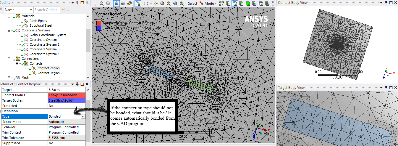
SubscriberHi, I designed a plate with an inclusion. The inclusion was placed on the matrix plate in the form of a steel strip. I want to see the SIF values at the end of the inclusion. However, I don't know how to define this since the inclusion and the crack are different structures. In my previous post, they said that the matrix material and the inclusion should not be bonded, but I couldn't find any further explanation. If I need to show the inclusion as a crack, how should I do this? Thank you in advance.
-
November 20, 2024 at 7:47 am
Harshvardhan
Ansys EmployeeHi,
The contact type between any two parts should mirror the real world conditions. Bonded contact between inclusion and parent material will not create a crack front. (Example: a pebble in a concrete mixture) What contacts should be defined between the inclusions and parent materials should mirror how you expect them to interact in real world.
It should be helpful for you to go through some of the AIS coursework detailing the types of contacts. Here are some:
Contact Mechanics | Ansys Innovation Courses
9.6. Contact
I hope this helps.
Regards,
Harshvardhan
Ansys Help
Ansys Learning Forum (Rules & Guidelines)
-
- You must be logged in to reply to this topic.


-
3402
-
1052
-
1051
-
896
-
872

© 2025 Copyright ANSYS, Inc. All rights reserved.


