TAGGED: ansys-fluent, fluent, fluid-flow, heat-flux
-
-
March 7, 2026 at 6:11 am
mattindrawijaya
SubscriberHi everyone,
I am trying to simulate water flow in a straight pipe in ANSYS Fluent. My setup:
Straight pipe with identical inlet and outlet cross-sections
Mass Flow Inlet = 0.0083 kg/s (30 kg/h)
Pressure Outlet = 0 Pa gauge
Walls set with heat flux or adiabatic
Inlet Temperature: using an Expression to mimic a “closed-loop” temperature cycle
The issue:
The fluid flows correctly, but the outlet temperature does not increase at all
The Expression I used tries to set inlet = outlet, but it seems Fluent cannot read the outlet temperature in real-time
I cannot use a UDF, and Periodic BC does not appear in the boundary type dropdown
- I use 1000 W/m2 for the heat flux input properties
My questions:
Is it expected that Expressions alone cannot make the inlet follow the outlet?
What is the best approach to create a straight pipe closed-loop thermal setup without using a UDF or Periodic BC?
Are there any common settings for flow or boundary conditions that I might be missing, which could cause the outlet temperature to remain stagnant?
Thanks in advance for your help!
-
March 9, 2026 at 10:53 am
Essence
Ansys EmployeeHello,
If you have applied adiabatic BC at the walls, then is there any other means of heat transfer in/out of the domain?
-
March 9, 2026 at 12:25 pm
mattindrawijaya
SubscriberSorry, i didn't mean to do the adiabatic, i use heatflux on the top surface and the outlet temperature still does not increase at all, even when i tried with the constant inlet temperature it still doesn't work. Is there any solution of how to fix this problem? Thank you!
-
-
March 9, 2026 at 1:59 pm
Essence
Ansys EmployeeHow is the mesh quality? Are you simulating a steady or a transient case? You can use profiles to achieve the closed loop cycle.
-
March 9, 2026 at 2:57 pm
mattindrawijaya
Subscriberthe orthogonal quality minimum is 0,24336. maximum 1, and the average is 0,99845. standard deviation is 1,7656e-002.
skewness minimum 1,3057e-010. maximum 0,78237. and average 7,2574e-003.
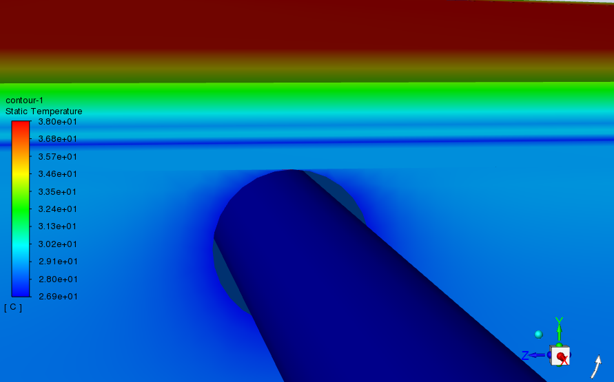
I am currently simulating a transient case for a solar panel cooling method with PCM and Metal foam with a fluid flow inside a pipe that goes through the PCM and i was hoping to make a closed loop system from the pipe used in the system, but the fluid doesn't seem to be flowing through the pipe, even though I already gave the mass-flow rate on the inlet BC and using the constant thermal inlet BC and heat flux on the top wall surface for 1000 W/m2.
I can not use the profiles since the outlet temperature does not increase along the simulation at all. Is there any solution for this problem?
-
March 10, 2026 at 8:24 am
Essence
Ansys EmployeeInitially, don't use the closed loop cycle. Just try to simulate with inlet and outlet and then see if the outlet temperature increases or not. Simulate the case in steady state.
Afterwards switch back to transient.
-
-
-
- You must be logged in to reply to this topic.
-
6039
-
1906
-
1425
-
1308
-
1021
© 2026 Copyright ANSYS, Inc. All rights reserved.
