-
-
October 24, 2023 at 8:34 am
derek1414
SubscriberTo whom it may concern,
My ultimate goal is to conduct a Semi-periodic simulation using 3D components. In this process, I have encountered two issues.
First, my approach involves using a lattice pair and radiation boundaries to excite the incident wave from the input plane and extract 3D components for finite array simulation.
When conducting a simulation using Floquet ports, the reflection magnitude and phase of S11 are correctly plotted. However, when I use the incident wave for simulation, the reflection magnitude is well plotted, but the phase remains consistently at 0 degrees. How can I ensure that both sets of results are consistent?
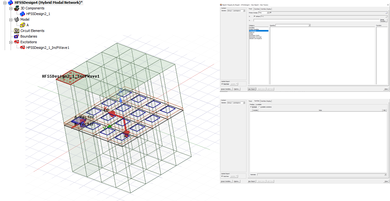
Second, I've created a unit cell using the incident wave and exported it as a 3D component. I then imported this component into a hybrid simulation to create a 4x4 array. The simulation was completed successfully, but I couldn't extract S-parameters. How can I extract S-parameters in this scenario?
Thank you very much for your time.
-
November 3, 2023 at 2:47 pm
Aymen Mzoughi
Ansys EmployeePlease open a support case under customer.ansys.com and upload your design for a closer look
-
- The topic ‘floquet port simulation using incident wave’ is closed to new replies.


-
3367
-
1050
-
1047
-
886
-
831

© 2025 Copyright ANSYS, Inc. All rights reserved.


