

-
-
February 18, 2022 at 8:35 am
mimozas1
SubscriberHalllo. I am working on a 3d wing simulation. I have a C-TYPE mesh and domain as the image shows.
February 18, 2022 at 9:48 amRob
Forum ModeratorIf the facets don't exactly align you can't use the "normal" periodic options. Have a look in the non conformal interface options: you can use those to create periodics. Chances are your mesh nearly lines up but is out of tolerance somewhere.
However, if the flow is aligned with the wing just set a symmetry plane or use 2d. If it's not aligned you need to refine the mesh in the z-direction as 3 tet cells isn't enough.
February 19, 2022 at 1:53 pmSubscriberFirst of all, thank you Rob for your immediate reaction to my question! It really helped.
I fixed the problems based on your advice but another one occurs. When i manually create the periodic b.c. with the left and right surcafe of the domain, i leave the box (matching, mapped, coupled) unchecked. So ansys creates a pseudo-surface to unite the two surfaces i impose the interaction and the periodic bc. My problem is that i want to specify the periodic conditions with 0 mass flow rate and 0 gauge pressure. But when i run the simulation occurs a floating point exception from the first iteration
The cause of this error might be the type of the pseudo-surfaces created?? (they are left to wall). If not do you have any other ideas?
Thanks a alot for your help and your time!
February 19, 2022 at 1:56 pmSubscriber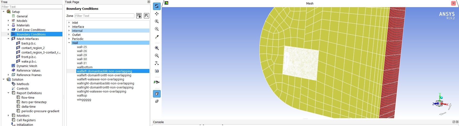
February 19, 2022 at 1:56 pmSubscriber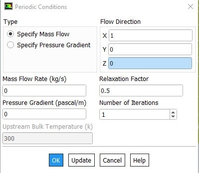
February 19, 2022 at 1:56 pmSubscriber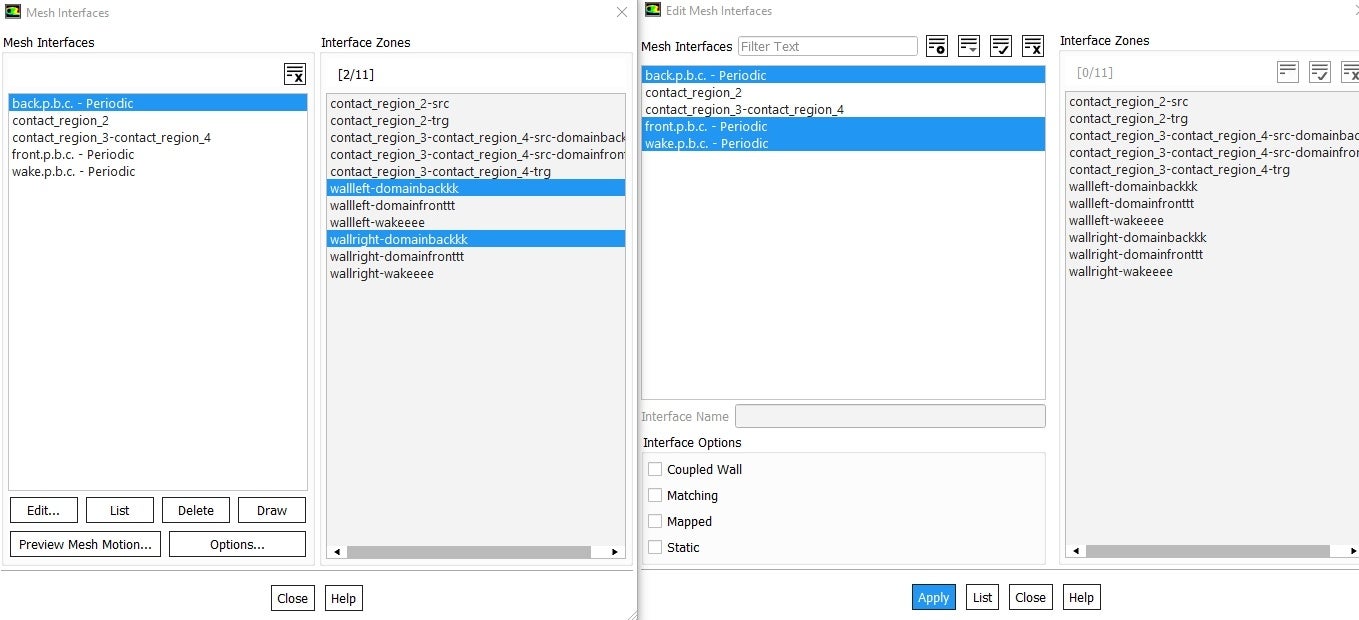
February 21, 2022 at 9:33 amSubscriber


February 21, 2022 at 9:40 amForum ModeratorIf there's zero flow and pressure then why are you using periodics? That implies the flow is parallel to those surfaces. You also set the periodic flow vector for the periodic bc, so x=0, y=0 and z=1 in this case.
February 21, 2022 at 4:22 pmSubscriberThank you.
I corrected the vectors. With that adjustment the model runs without errors!
February 24, 2022 at 5:53 pmSubscriberHallo Rob!
I am responding to your question about the reason i am using periodic b.c. if i have 0 mass flow rate and 0 gauge pressure.
The fact is i made i mistake. I didnt want to have 0 net rate but i wanted to achieve the following: everything that happens in one p.b.c.Face to happen to the next p.b.c.Face. Thinking about it again i think the most correct option would be to select GaugePressure0.
I would appreciate your opinion on this!
Thanks in advance for your help to us users!
Mimis.
February 25, 2022 at 10:50 amForum ModeratorIf the inlet flow is aligned with the geometry then the cross flow should be zero. Adding periodic boundaries may mean the solver adds a small cross flow, but that ought to be damped out as the solution converges. If you want to create a cross flow you need to resolve across the domain too.
March 2, 2022 at 10:49 amSubscriberI have the inlet velocity to bem parallel to the chord of the wing. That means there is no spanwise velocity. But the velocity on top of the wing may have a spanwise velocity due to turbulent effects. That is why i want to add the periodic b.c.
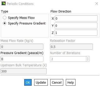
I think makin the periodic conditions as Gauge Pressure 0 will do. But i am not sure if i have to make it on z or on x axis, as shown in the next picture.
March 2, 2022 at 11:55 amForum ModeratorIf you want to pick up that you'll need a wider domain and a lot more resolution.
March 2, 2022 at 8:35 pmSubscriberYes, i am aware of that. I am just running a quik simullation to get acquainted with the physical model and not to get some good quality results.
Once i do this, i will work on mesh resolution more.
But the thing i am still trying to find is whereaw to have the GaugePressure=0 in flow direction of Z or X, according to what i described you about on my previous question.
Thanks a lot!
March 2, 2022 at 8:37 pmSubscriberI think that it must be on Z axis but i am not really sure.
I think it is Z because the two periodic bound.conditions are perpendicular to this axis.
March 3, 2022 at 12:03 pmForum ModeratorZ is the direction of the periodic flow. https://ansyshelp.ansys.com/account/Secured?returnurl=/Views/Secured/corp/v221/en/flu_ug/flu_ug_sec_periodic_overview.html covers the limitations.
Viewing 15 reply threads- The topic ‘Floating point on ansys Fluent with periodic boundaries.’ is closed to new replies.
Innovation Space Trending discussions
 Top Contributors
-
peteroznewman
 6775
6775 -
scabo
 1906
1906 -
Dennis Chen
 1490
1490 -
javat33489
 1330
1330 -
NickFL
1147
Top Rated Tags
© 2026 Copyright ANSYS, Inc. All rights reserved.
Ansys does not support the usage of unauthorized Ansys software. Please visit www.ansys.com to obtain an official distribution.
-


The Ansys Learning Forum is a public forum. You are prohibited from providing (i) information that is confidential to You, your employer, or any third party, (ii) Personal Data or individually identifiable health information, (iii) any information that is U.S. Government Classified, Controlled Unclassified Information, International Traffic in Arms Regulators (ITAR) or Export Administration Regulators (EAR) controlled or otherwise have been determined by the United States Government or by a foreign government to require protection against unauthorized disclosure for reasons of national security, or (iv) topics or information restricted by the People's Republic of China data protection and privacy laws.
