TAGGED: design-optimization, displacement, load-case, torque, validation
-
-
May 15, 2025 at 4:02 pm
YuuZena
SubscriberAs a student working on my diploma thesis, I'm developing a custom Force/Torque sensor requiring a flexible chassis. My design needs specific displacement constraints (0.4-0.6mm) at target points under combined loads (forces/torques).
After multiple failed attempts with ANSYS, I'm questioning if this is possible. Has anyone successfully implemented similar constraint-driven generative design?
I can share my detailed requirements document with anyone willing to advise. (Swisstransfer - PDF Document) Looking for guidance on appropriate workflow and settings rather than having someone complete it for me.
Thanks in advance for any insights!
-
May 19, 2025 at 6:05 am
Ashish Khemka
Forum ModeratorHi,
Ansys employees cannot look at the attached files. For applying displacement constraints – try applying ‘Nodal Displacement’ for the nodes in between 0.4 to 0.6mm. You can use ‘Named Selection’ to select the nodes in the given range.
11.2.2. Specifying Named Selections using Worksheet Criteria
Regards,
Ashish Khemka
Introducing Ansys Assistant a 24/7 AI-powered virtual assistant for active Ansys academic customers. -
May 20, 2025 at 7:08 am
-
May 20, 2025 at 12:15 pm
John Doyle
Ansys EmployeeIt looks like you have defined a Design Domain and you have the materials, loads, boundary conditions, and response constraints (i.e. displacment limits at strategically scoped surfaces). I would recommend running your static analysis on each of the load cases and feed them into the Topology Optimizer with the objective to minimize compliance (maximize stiffness) for the given response constraints. You could choose to remove material from the design domain or run the shape optimizer to just rearrange the design domain shape without changing the volume. Maybe start with just one load case to establish a good workflow first. Please refer to the online Documentation for "Structural Optimization in Mechanical" for more details.
Regards,
John
Introducing Ansys Assistant a 24/7 AI-powered virtual assistant for active Ansys academic customers.
-
May 20, 2025 at 12:49 pm
YuuZena
SubscriberThank you, John, for your guidance. I've already implemented 72 load cases and completed the mechanical simulation as well as a stiffness optimization variant. However, I'm facing a specific challenge with the displacement constraints.
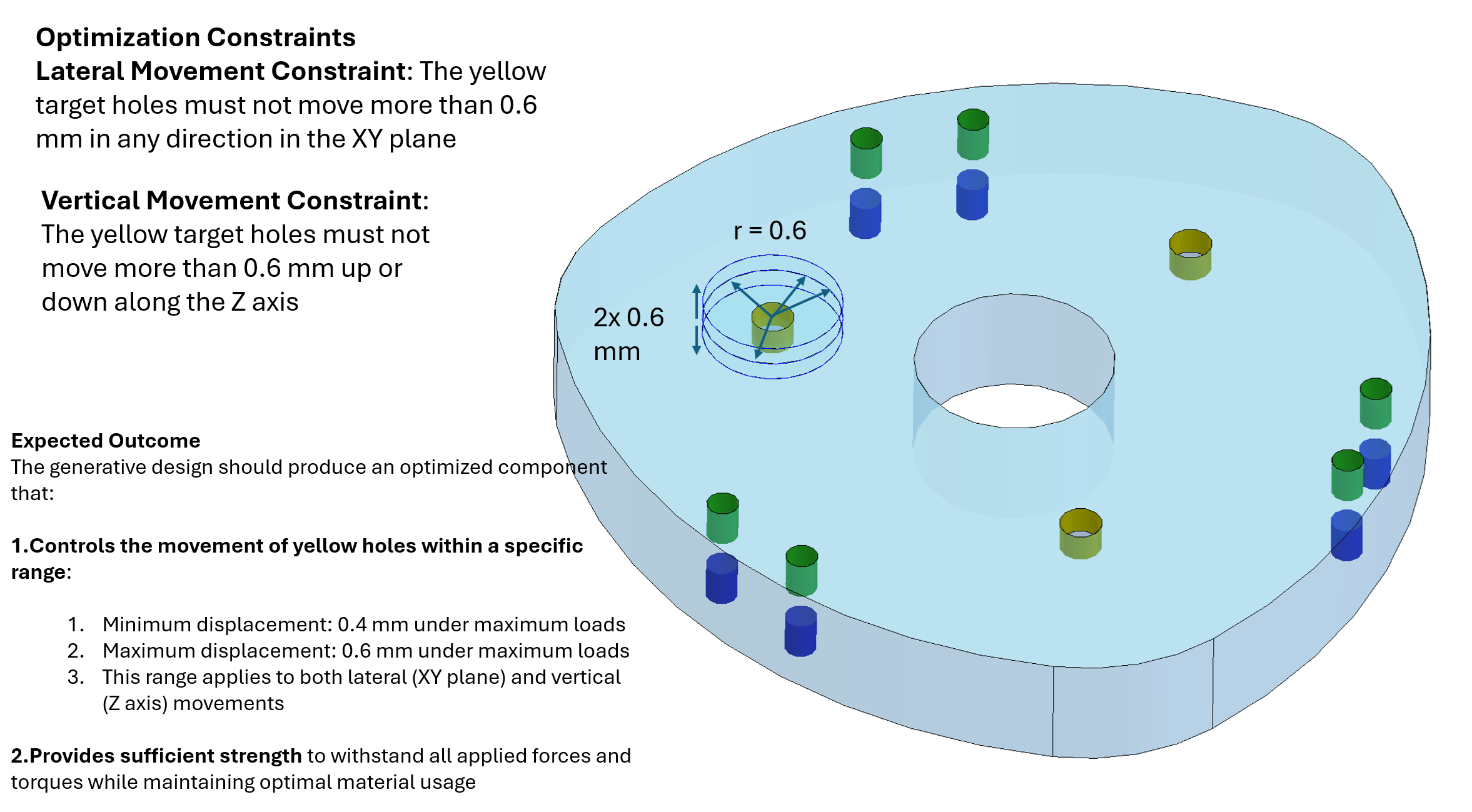
My issue is that I need to define a specific movement range (0.4-0.6mm) for the holes, but only at peak loads - not across all load cases simultaneously. The structure should flex linearly during the ramp-up phases between load cases, but reach this 0.4-0.6mm displacement specifically at the peak loading conditions.
I've tried using the User Defined Criterion for displacement and Primary Criterion for the Mechanical simulation, but I'm struggling to properly define these peak-specific constraints. When I use criterion constraint with the 0.4-0.6mm movement limit, it seems to only apply to a single step rather than properly constraining the peak displacement across the relevant load cases.
Could you advise on how to properly set up these displacement constraints to ensure the target areas maintain the required 0.4-0.6mm displacement range specifically at peak loads, while allowing linear flexibility during the ramp-up phases?
Thank you for your continued assistance.
-
- You must be logged in to reply to this topic.
- NA
- Response constraint not allowing structural optimization to solve.
- Protected Depth Topology Optimisation
- how to get stress at a node and put it in a parameter for use with optimization
- Fluent Editor Error
- Add Parameter so existing set
- optislang tutorial: damped oscillator calibration
- OptiSlang does not create LsxDefs while importing LS-DYNA output
- Feasibility Check – FT Sensor Flexible Chassis Design Optimization
- Structural Optimization
-
3134
-
1002
-
917
-
858
-
792
© 2025 Copyright ANSYS, Inc. All rights reserved.