TAGGED: 3DFDTD, interconnect, Lumerical-FDTD, port-setup
-
-
May 21, 2024 at 6:53 am
Sujal Gupta
SubscriberWe need guidance regarding the exporting a multi-input (say 3) and multi-output (say 2) port structure from FDTD simulations to use in Interconnect as one of element. Specifically, we require assistance ensuring that the imported FDTD model in Interconnect seamlessly integrates with the control of exported structure internal properties (internal physics), such as geometry changes (say change in port width), which will also incorporate the corresponding results (say transmittance).
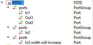
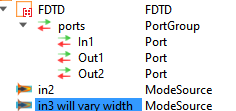
Below are possible approaches I thought of:
Please advise which approach is correct to get S-parameters that can be used in Interconnect. If both are wrong, please guide, how it can be done.
It would be great if you can refer some of the contet for this as well as, scripting to extract S-parameters for above case.
Thank you.
-
May 23, 2024 at 6:22 pm
GWANG
Ansys EmployeeHi Sujal Gupta,
Thank you for the post. Could you please let me know some details on your applications? For example I understand that you want to sweep through the port waveguide width, and is this for a single wavelength or for a sweep of wavelength as well? Overall I would recommend using the port object, but you don't need to add multiple versions of it for different structure. Instead, you may use a large enough port that when the port waveguide width changes the port can always capture the full mode.
-
May 24, 2024 at 10:59 am
Sujal Gupta
SubscriberThank you, G. Wang for reply.
There is no direct application as such.
I understant you point. Just want to ensure it again. As you mentioned I shall keep my port width large/wide that will capture the exited mode even when the width of waveguide is incresed.
One more things that yet to be clearify:
Since I want to cotrol/change the width of one of waveguide from Interconnect, not in FDTD. So, how I shall I export my FDTD s-parameter for interconect.
- Do I need to first sweep the width of that waveguide before extracting s-parameter so that FDTD model can acknowledge the width varriation command from received from Interconnect. If so, does the s-parameter sweep itself capture the width sweep and genetate all the s-parameter corresp[onding to variation of width.
- If not, then how the s-parameter shall be exported.
Thank you.
-
May 24, 2024 at 11:24 am
Sujal Gupta
SubscriberThank you G. Wang for reply.
There is no direct application as such.
-
May 24, 2024 at 11:25 am
Sujal Gupta
SubscriberI understand your point and I considered it.
I just want to assure it will be okay. As you mentioned I shall keep the width of the waveguide large enough so that when the width is increased the port can excite the mode as per the dimension of the waveguide. And extracted s-parameter will account both I/O form a port in the Interconnect. Even though in FDTD only one port can be assigned as sourse while rest are destination.
One more thing yet remain: I want to control/change the width of the waveguide from the interconnect, not in FDTD. So how shall I export the s-parameters of FDTD for Interconnect.
1. Shall I just take s-parameter sweep then export it for interconnect (Which appear wrong to me as there is no direct way where one can change the width of waveguide in interconnect; which is itself exported from other solver (here FDTD). If there is let me know how to do it).
2. Or I shall first take the waveguide width sweep in FDTD then take the s-parameter sweep. In that case does s-parameter extraction would itself account for variation in width of waveguide or any other sweep.
3. If not the 2nd then how, we can do it (if scripting require please share any example).Thank you.
-
May 24, 2024 at 9:45 pm
GWANG
Ansys EmployeeHi Sujal Gupta,
Yes if you have large enough ports then you don't need to change the port when sweep through the port waveguide width. Please note that the ports shouldn't be overlapped with each other, and please visualize the mode profile to make sure the port size is good for all the port waveguide width. Regarding the sweep question, option 2 is the one to use. The s-parameter sweep only sweeps through the ports to generate the full s-parameter. You can use it with a regular sweep (which sweeps through the waveguide width) to export the full s-sparameter.
-
- The topic ‘FDTD Model for Interconnect Element’ is closed to new replies.


-
3487
-
1057
-
1051
-
945
-
917

© 2025 Copyright ANSYS, Inc. All rights reserved.


