TAGGED: Lumerical-FDTD, photonics, port-setup, ports
-
-
July 17, 2024 at 8:52 am
tim.fuhrmann
SubscriberHello,
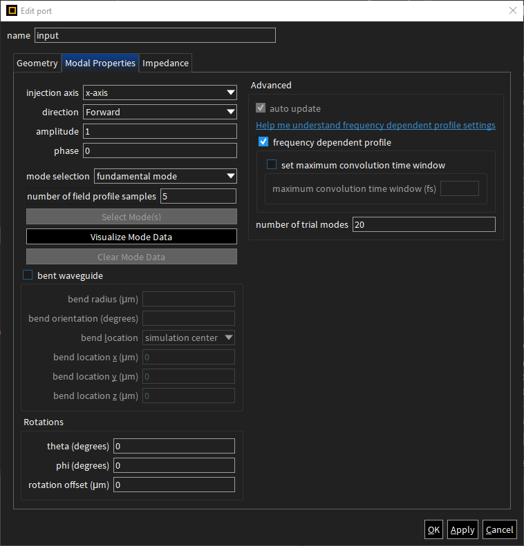
I am simulating a waveguide with a ring next to it with FDTD. I added two ports, one for the output and one for the input. The modal properties are the follwoing for the input port.

If I click on Visualize Mode Data I get the follwoing errors:
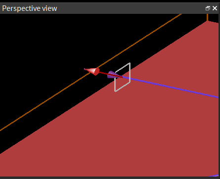
As shown in the follwoing picture the waveguide is within the port.
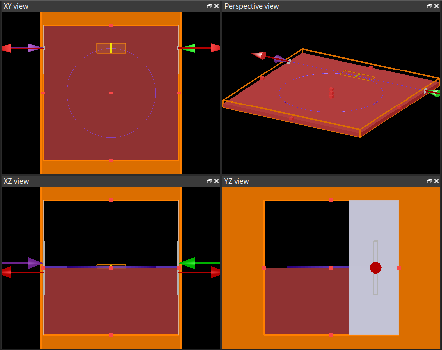
The overall layout is the following:

I am happy about any hint. Thank you in advance,
Tim -
July 17, 2024 at 3:50 pm
Greg Baethge
Ansys EmployeeHi Tim,
Thanks for posting your question. Could you check the mesh over the waveguide? The PML boundaries look quite thick, that typically happens either when using a large number of layers or when using a coarse mesh. So I would check the mesh size over the waveguide with respect to the waveguide dimensions and the wavelength range.
-
July 18, 2024 at 6:18 am
tim.fuhrmann
SubscriberHi Greg,
thank you for your quick reply. Changing the mesh settings and changing the tickness of the PML boundaries worked perfectly, thank you.
Best,
Tim -
July 18, 2024 at 8:39 am
Greg Baethge
Ansys EmployeeYou're most welcome, Tim, glad I could help!
-
- The topic ‘FDTD error: The source is not large enough to calculate a mode’ is closed to new replies.


-
3437
-
1057
-
1051
-
902
-
896

© 2025 Copyright ANSYS, Inc. All rights reserved.


