Ansys Assistant will be unavailable on the Learning Forum starting January 30. An upgraded version is coming soon. We apologize for any inconvenience and appreciate your patience. Stay tuned for updates.
General Mechanical

General Mechanical

Topics related to Mechanical Enterprise, Motion, Additive Print and more.

Face Meshing Problem

    • thach-hoang.nguyen
      Subscriber

      Hello,

      I have a problem with face meshing the structure like in the photo 1. I want to have more layers and i've tried to choose an element size for the surface but instead it meshed the thickness of the structure (photo 2). I've tried face meshing but it didn't work also. Can someone have an ideal how to obtain more layers on the surface?

      Thank you and have a nice day!!

    • Sampat Kumar
      Ansys Employee

      Hi Hoang NGUYEN,
      What types of local meshing control did you use for this mesh?

      You can try selecting the edge of the face, then selecting the "sizing" option to mesh the surface.The desired element size will depend on the specific dimensions and level of refinement you need for your geometry.

      Best Regards,
      Sampat


    • thach-hoang.nguyen
      Subscriber

      Hello,

      I'm using Multizone Haxahedral to create the mesh. I've tried sizing like you mentionned but it didn't work.It always meshed the thickness if i do that. My structure's thickness is 3 times greater than the width ( in your photo, the width is bigger than the thickness). And the head of my structure is more complex. Do you have any ideal?

      Thank you

      Best Regards,

      Hoang

    • thach-hoang.nguyen
      Subscriber

      Here is some photos of the mesh which i used multizone Hexahedral and Edge Sizing. The first photo is with only multizone and the second is Hexahedral and Edge Sizing. It only concentrate meshing the thickness not the width which i need to mesh. Thank you

    • peteroznewman
      Subscriber

      Open the geometry in SpaceClaim. Add a Plane and use the Move Tool to position the plane as shown below.

      Use Split Body to slice the solid into 3 parts. Use the Combine tool to reattach the top part to the the right leg.

      On the left leg, look to see if there is more than one face on each side of the leg. On the Repair tab, use Face Merge to combine faces. You want exactly 6 faces on that leg.  Click on the Split Edges button to eliminate extra vertices in the geometry. On the Prepare tab, click the Share button.

      Open this geometry in Mechanical. Right click on Mesh and Show Sweepable bodies. The left leg should highlight in green.  Now you can insert a Mesh Method and select Sweep.  If you pick the left side face as the Source face, you can type in the Sweep Number of Divisions to be as many elements across the front face as you want.

    • thach-hoang.nguyen
      Subscriber

      Hello Peter,

      I'm looking to your method right now. But may i ask if there is another way more efficient. I'm woking on the stent model in this is just a little part of the stent. So if i work on other legs of the stent that will be a lot of things to do 

      Thank you and have a good day

    • peteroznewman
      Subscriber

      Hello Hoang,

      I have a lot of experience meshing stents. The trick is to create all the planes of symmetry so you can cut the entire stent down to two tiny pieces, one end piece and one adjacent piece. Clean the geometry on those pieces then use the Mirror tool to reflect one piece once along the axis and once across the plane through the axis. Make sure to keep turn off Merge. You want lots of small bodies. Use the pattern tool to copy the body along the axis to the center plane. Use the pattern tool to copy the body around the axis. The other piece will be from the end of the stent. Repeat those steps to populate one end. Finally use the Mirror tool to reflect all the bodies about the center plane to create the other half of the stent.

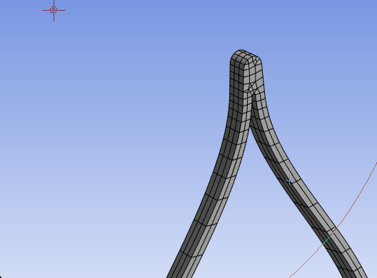
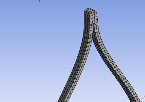
      In Mechanical, if you set the Default element size to 1/4 of the wall thickness and set the Element Order to Linear, you should get exactly 4 elements through the wall thickness and have nice uniform mostly hex and some wedge elements on the stent.

      Meshing will be fast because of all those small bodies are so simple to mesh and the meshing code will run in parallel on multiple cores to mesh them.

      Insert a Mesh Edit object under the Mesh branch of the outline and under Mesh Edit insert a Node Merge Group and then Detect Connections. This will connect the nodes across all the bodies.

      An alternative is to use the Share button in SpaceClaim, then you don't have to do a Node Merge, but you might not get the same mesh and it may take longer to mesh.

    • thach-hoang.nguyen
      Subscriber

      Hello Peter,

      I've tried like you said about cutting the stent into pieces and finally it worked! Thank you for your advices. But i only managed to mesh one ring of the stent. But my stent has a lot of ring. To be efficient, is there anyway to copy the mesh from the first ring to other rings? I've tried to use Mesh Copy but Ansys doesn't like copying from multiple surfaces ( divided surface) to one surface!

      Thank you again and have a good day

    • peteroznewman
      Subscriber

      It's better to build the geometry in SpaceClaim for the entire stent. If you have one ring built, use the linear Pattern to create all the other rings. The first end ring would be reflected about the center plane to get the other end ring (which may need to be clocked).

      I use other meshing software (Femap) to copy/translate meshes and merge nodes, so I haven't tried to figure out how to do that in Ansys.

Viewing 8 reply threads
  • The topic ‘Face Meshing Problem’ is closed to new replies.
[bingo_chatbox]