-
-
July 13, 2023 at 10:46 pm
omarb
SubscriberI am trying to extract the series inductance of an open (capacitive) structure
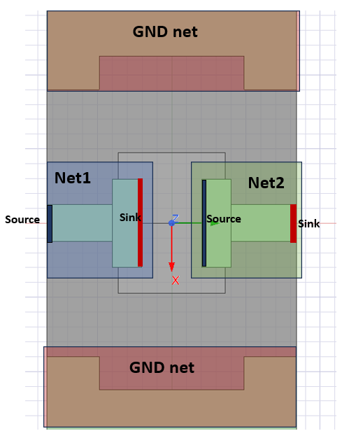
The structure is connected in a 2-port approach with coplanar wave guides as below:I am assigning a net on the signal path on the left and another net in the signal path to the right. GND nets are added to the ground planes. Then I add a source at the input and a sink at the open end, as below :
Finally, I simulate and sum the individual self-inductanes of the 2 nets. Is this approach recommended?
Also, I noticed that removing the gnd nets dont affect the result. Shouldnt they count as a return path?
Any feedback is well appreciated.Thank you!
-
July 18, 2023 at 10:01 pm
Irina Gordion
Ansys EmployeeI assume the tool used is Q3D. To answer the last question why "removing the gnd nets doesn't affect the result": Q3D calculates partial inducatnce; if Ground nets do not have Sources/Sinks defined, they don't affect inductance values and return path is not considered.
The question "how to extract the series inductance of an open (capacitive) structure" looks strange to begin with. Please, clarify how would you use the value.
-
July 19, 2023 at 7:30 pm
omarb
SubscriberThank you for your reply. Yes you are correct the simulation was carried on Q3D, I apologize for not clarifying this.
The simulation is basically an open between two conductors, it is intended to work as a capacitor in a microwave passband filter that we fabricated. However, our measurements show a self-resonance of this standalone structure (the picture above) due to its series self-inductance. This self-inductance value is what we are trying to characterize in Q3D and match with our measurements, so that we can optimize for the self-resonance to be outside the filter operation bandwidth.Regarding the ground nets, I am not able to add sinks or sources to it. I can select a face within the ground net geometry and assign a source/sink to it, but in the project manager on the left that source or sink is just floating,it doesnt go into the hierarchy of the ground net for some reason. It seems like signal and sink sources can only be assigned to signal nets.
Thanks again for the feedback.
-
July 19, 2023 at 10:58 pm
Irina Gordion
Ansys EmployeeI think the more accurate way is to use HFSS design with ports; a capacitor can be modelled as lumped RLC element with parameterized capacitance. If you want to stay in Q3D, assign all nets as signal nets with sources/ sinks and explore Reduce matrix operations
-
- The topic ‘Extracting series inductance of an open structure’ is closed to new replies.


- How does Ansys Twin Builder implement different simulation steps for subcircuits
- Ansys-MATLAB Co-Simulation
- Compute near field simulation with current
- Ansys Resonance simulatioin error
- Double-sided LIM external circuit error
- Calculating E-field tangential to a 2D resonant structure on a sapphire chip

-
2783
-
965
-
846
-
599
-
591

© 2025 Copyright ANSYS, Inc. All rights reserved.


