-
-
January 13, 2025 at 9:18 am
anujchauhan10339
SubscriberProblem Description:
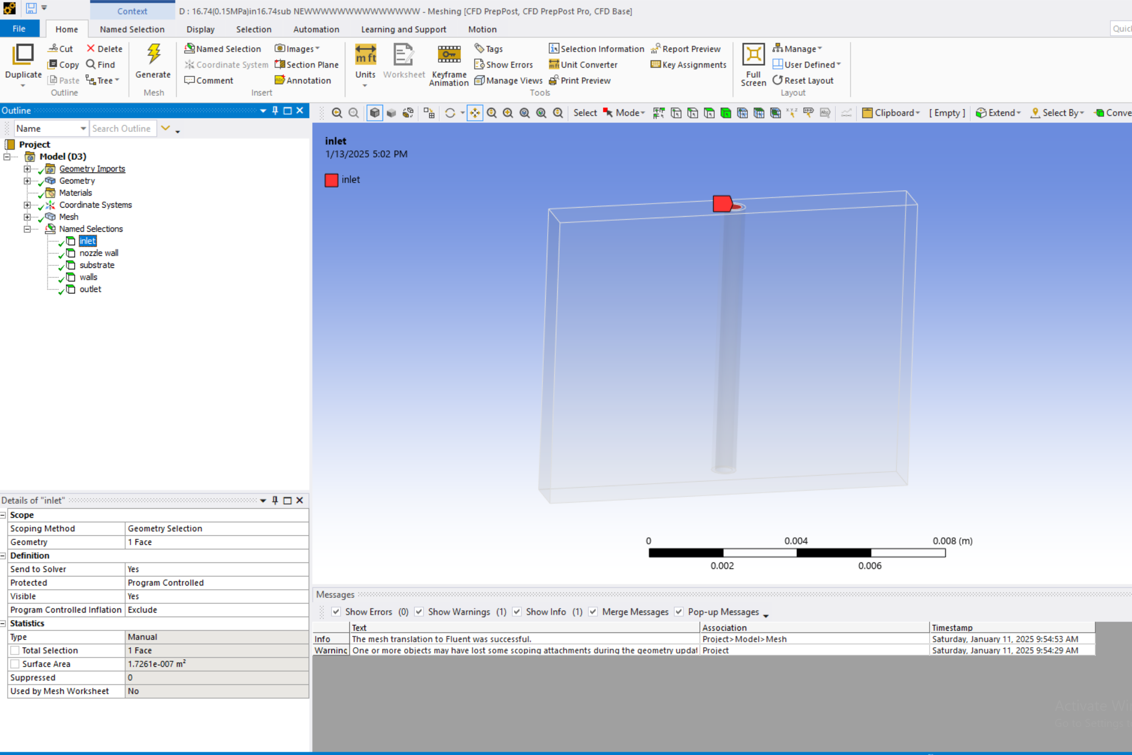
I am simulating the extrusion of fluid (high-viscosity fluid) through a needle (diameter: 0.47 mm, length: 8 mm) using a multiphase VOF model in ANSYS Fluent. The inlet is set to a pressure inlet of 0.05 MPa, and the substrate moves at 30 mm/s, positioned 0.5 mm below the needle tip.
In this case io want to see the fluid behaviour (Dispensed line ) lon the substrate. Instead of moving the needle (DUe to computation limitations), I am trying to move the substrate in the opposite direction to see the fluid dispensed line on the substrate. When I use the very low substrate speed (30mm/s), The fluid stores at one place which i understand and in case of higher substrate speed the dispensed line is perfewct as i can see using isosurface curve.But Here my main concern is, when i go for the initialization (inlet Pressure BC) the valocity values shown by ANSYS is around 10m/s which is quite high.
Issues:
- During initialization, Fluent shows unrealistically high outlet velocities (~10 m/s)
while the theoretical velocity at 0.05 MPa is much lower (~0.0288 m/s, calculated using Hagen-Poiseuille).
- On the moving substrate, the dispensed Vaseline fails to form a continuous line due to the high relative velocity between the fluid and the substrate (substrate: 30 mm/s).
Question:
I have uploaded the simplified geometry. Could anyone please guide me on
Why does Fluent calculate such high velocities during initialization? Am I making a mistake in my setup, and how can I ensure the relative velocity matches the substrate speed for proper deposition?
Thank you for your assistance! 
- During initialization, Fluent shows unrealistically high outlet velocities (~10 m/s)
-
January 13, 2025 at 10:27 am
Rob
Forum ModeratorCheck the phase definitions. If you're looking at Hybrid Initialisation, that's (I think) a Laplacian solution, and may not be picking up the viscosity: it's a starting point and there's a reason for the Patch function.
I'd also tend to use a velocity inlet for the liquid as they're generally more computationally stable.
-
January 13, 2025 at 10:34 am
anujchauhan10339
SubscriberThank you for the reply. I have tried with the hybrid initialization as well but still the simulation is far away from the experimental one. (The only differemnce is , In experiment the syringe or the needle is hold by the xy moving device.) but in simulation I am moving the substrate
Actually I am using inlet pressure in my experimental setup and want to use the same condition for the simulation. Using the pump and a dispensing machine I am using inlet pressure in the rangeo of 0.05Mpa to 0.2MPa and want to see the dispense fluid line onto the moving substrate so that I can see the dispensed line.
But as at 30mm/s of substrate speed , The fluid is storing at one place.-
January 13, 2025 at 11:19 am
anujchauhan10339
SubscriberI have set the substrate as a moving wall in the boundary condition. Is this way correct?
-
-
January 13, 2025 at 11:15 am
Rob
Forum ModeratorHow are you moving the substrate?
-
January 13, 2025 at 11:27 am
Rob
Forum ModeratorMoving wall may not pull material away well. What are you actually seeing, and is the mass flow of liquid what you're expecting?
-
January 13, 2025 at 2:51 pm
anujchauhan10339
SubscriberActually I want to simulate the extrusion printing Using Fluent. But instead of moving the nozzle I am trying to move the substrate since I have no idea about how to move the nozzle using Oblverset Meshing or Dynamic Meshing.
so basically Its for the extrusion printing Using Fluent -
January 13, 2025 at 2:52 pm
anujchauhan10339
SubscriberDo you think its a good idea? Will it be same as moving the nozzle ?
-
January 13, 2025 at 3:03 pm
Rob
Forum ModeratorThe approach is OK, but having a moving wall may not drag material away as well as you'd like. As you've not shared any images I have no idea what the result looks like.
-
January 13, 2025 at 3:15 pm
anujchauhan10339
Subscriberi am sorry, I should have uploaded the initial results I achieved. I will upload the results tomorrow as I have already left my school today. I am uploading a contour curve (although its not very clear as it was in my mobile). I will upload the isosurface results which will make the pucture more clear.

-
January 14, 2025 at 1:02 am
anujchauhan10339
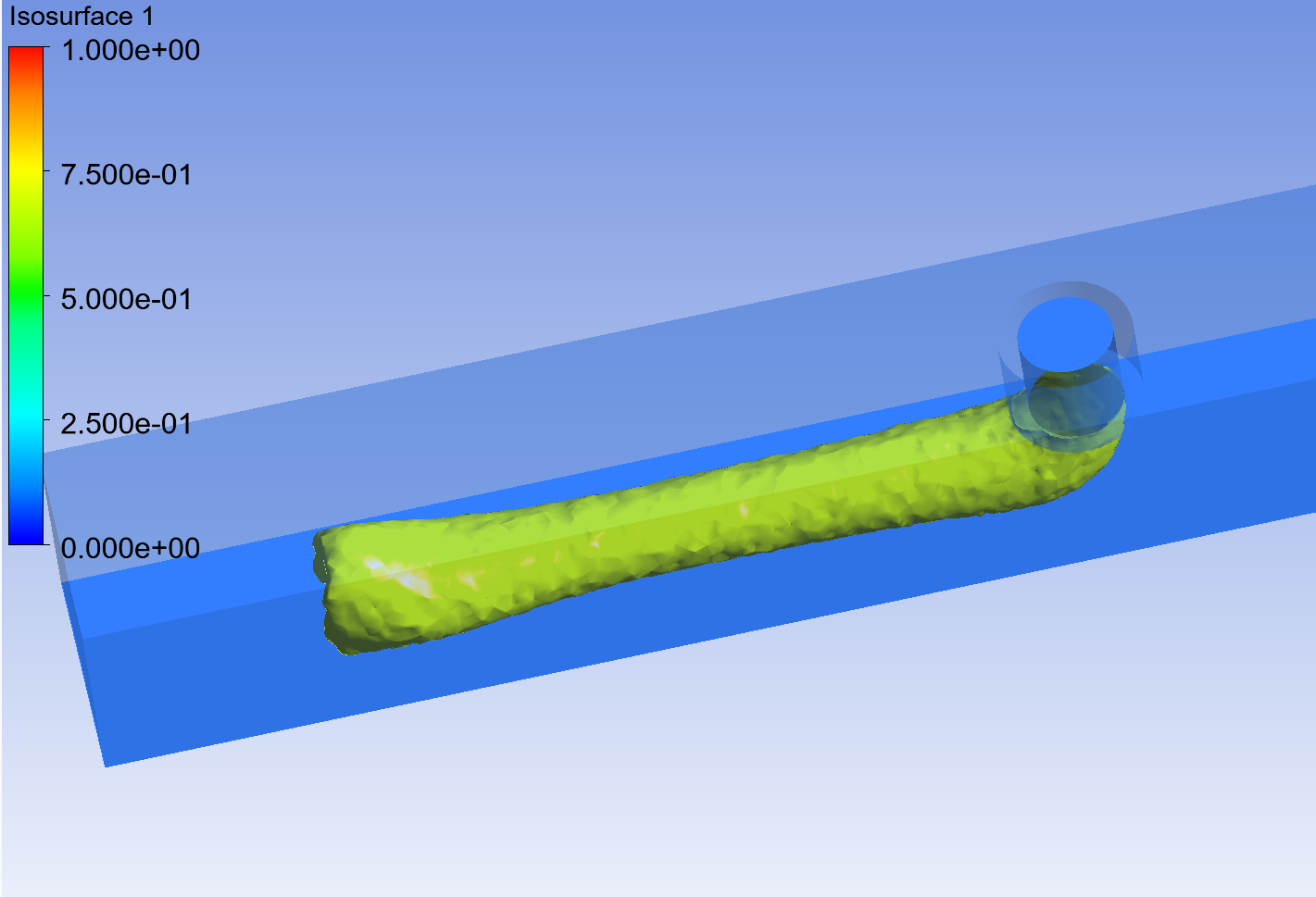
SubscriberHere is the result I am getting for the high sibstrate vale. Can see the flow of fluid on the substrate through the isosurface. But when i use the lower velocity the fluid store at one place mean not enough drag to move the fluid. I want to mimic the same case of the movement of nozzle and make a perfect dispensed line on the substrate.
-
January 14, 2025 at 9:37 am
Rob
Forum ModeratorIf the speed is too low it's reasonable for the inlet flow to overcome the bed motion and flow to go everywhere. It's also easy to do an experiment - toothpaste or caulking (easier to clean up than silicon sealant) can be squeezed onto a surface and the source moved.
-
January 15, 2025 at 3:11 am
anujchauhan10339
SubscriberYeah, It makes sense too me. I have donr the experiment where I choose body lotion.
COuld you guide me on how to move the syringe instead of moving the substrate as in my real experiment the nozzle is moving and dispensing the body lotion on the substrate with the speed around 20-30 mm/s.
But its kind of difficult for me to fix my simulation for the nozzle motion.
I am kinda beginner. -
January 15, 2025 at 9:55 am
Rob
Forum ModeratorHave a look at overset or dynamic meshing (layering).
-
- You must be logged in to reply to this topic.


-
2788
-
965
-
851
-
599
-
591

© 2025 Copyright ANSYS, Inc. All rights reserved.


